

Vacuum Feedthrough Overview and Engineering Challenges
Vacuum feedthroughs transmit electrical, thermal, or mechanical signals across vacuum boundaries while maintaining hermetic integrity. Their performance directly determines the stability and reliability of vacuum systems in semiconductor, aerospace, and scientific applications.
In vacuum engineering, one of the core challenges is enabling stable signal and power transmission into a sealed vacuum chamber while maintaining ultra-high vacuum (UHV) conditions. This requires balancing electrical insulation, thermal stability, and mechanical integrity under extreme environments.
Scope of This Engineering Review
This article systematically reviews key design considerations of vacuum feedthroughs, including advanced ceramic material selection, ceramic-to-metal sealing structures, hermetic sealing process control, and long-term reliability evaluation.
Vacuum Feedthrough Structure and Classification
Structure of Vacuum Feedthroughs
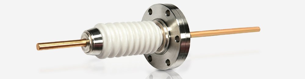
Vacuum feedthroughs typically consist of insulating ceramics, conductive pins, and metallic flanges.
- Insulating ceramics
Typically high-purity alumina ceramic, which electrically isolates the conductor from the flange and prevents high-voltage breakdown.
- Conductive pins
Used for transmitting current, high voltage, or low-level signals (e.g., copper, molybdenum, Kovar alloy).
- Metallic flanges
Responsible for mechanical connection and sealing with the vacuum chamber (e.g., CF, KF flanges).
Classification of Vacuum Feedthroughs
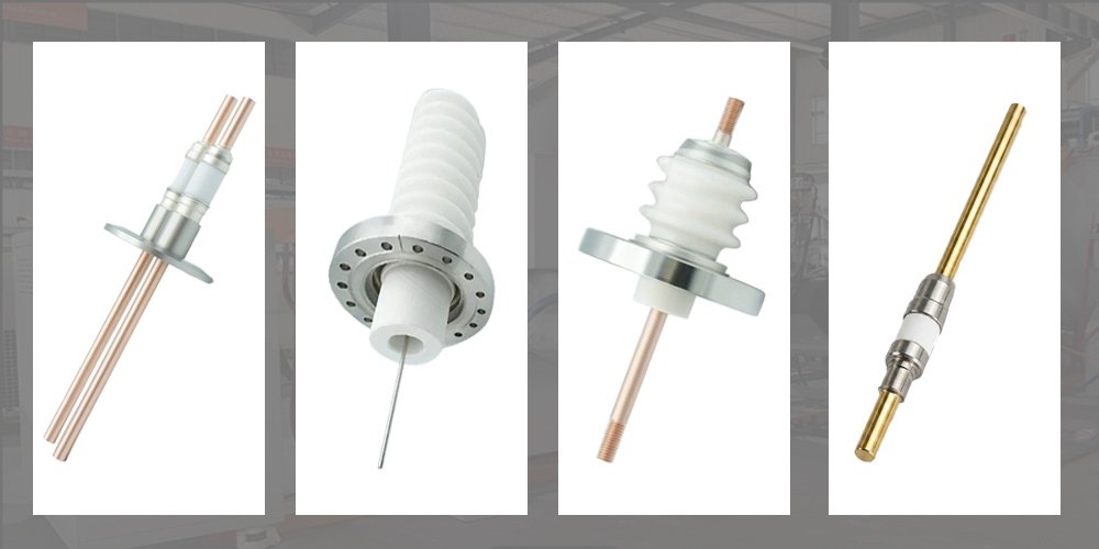
Vacuum feedthroughs can be classified based on transmission type and sealing structure.
By Transmission Medium
1. Electrical and power feedthroughs
Used to transmit current or electrical signals from atmospheric side into vacuum environments. Applications range from low-power signals to tens of kilovolts and hundreds of amperes.
Typical products include power feedthroughs, signal/multi-pin feedthroughs, thermocouple feedthroughs, and RF/coaxial feedthroughs.
High-purity alumina ceramic must be used as the insulating material to prevent high-voltage breakdown.
2. Fluid and gas feedthroughs
Used for transporting cooling water, process gases, or liquid nitrogen. These are usually all-metal welded structures.
However, if internal pipelines are connected to energized components, a ceramic insulating section (ceramic break) must be inserted to interrupt current conduction.
3. Mechanical motion feedthroughs
Used to transmit rotational, linear, or multi-axis motion. Commonly sealed using magnetic fluid seals or bellows structures.
If the internal stage requires electrical heating or bias voltage, precision ceramic insulating rings must be embedded inside the transmission shaft.
4. Optical and fiber feedthroughs:
Used to introduce optical signals, lasers, or visual observation paths. The main sealing materials are quartz, sapphire, or other transparent glass materials.
By Sealing Structure Type
1. Monolithic feedthroughs
Use metal brazing or glass-to-metal sealing to form permanent hermetic joints. Electron beam welding may also be used in metal-only designs.
Typical helium leak rates can reach ≤10⁻⁹ mbar·L/s in ultra-high vacuum applications.
These structures are widely used in UHV systems due to their high sealing reliability and low outgassing characteristics. Ceramic-to-metal sealing is used in similar high-reliability vacuum applications requiring electrical insulation.
2. Removable feedthroughs
Use compressible sealing elements such as O-rings or ferrules for repeated assembly and disassembly.
However, these structures require strict control of fit tolerances and compression force—insufficient compression leads to leakage, while excessive compression may damage internal conductors or fibers.
They are typically used in applications requiring frequent adjustments or replacement of consumables.
Material Selection and Structural Design for Vacuum Feedthroughs
Insulating Materials in Feedthroughs
- Alumina (Al2O3): The Standard Material Choice
Vacuum feedthroughs commonly use alumina ceramics due to their excellent electrical insulation, thermal stability, and cost-effectiveness. It is the most widely adopted material in industrial vacuum and ultra-high vacuum applications.
- Aluminum Nitride (AlN): High Thermal Conductivity Option
For applications requiring enhanced heat dissipation, AlN is often selected. Compared with alumina, it offers significantly higher thermal conductivity, making it suitable for high-power electronic and semiconductor systems. However, its cost and processing complexity are higher.
- Zirconia (ZrO₂): High Toughness for Demanding Conditions
Zirconia ceramics are used in specialized designs where higher fracture toughness and resistance to thermal shock are required. It is less common in standard feedthroughs but valuable in mechanically demanding or high-stress environments.
- Material Selection as a System-Level Trade-Off
Material selection is not a single-property decision, but a system-level engineering trade-off involving electrical insulation, thermal performance, mechanical strength, and cost.
- Impact of Ceramic Purity on Vacuum Performance
High-purity ceramics with dense microstructures help reduce outgassing and improve long-term hermetic stability. This is critical in ultra-high vacuum environments where leakage rates and surface contamination must be strictly controlled.
Comparison of Insulation Technologies in Vacuum Applications
Different insulation and sealing technologies exhibit significant differences in temperature resistance, vacuum compatibility, and mechanical strength.
Resin potting materials are generally limited to low-temperature applications below 200°C and are not suitable for high or ultra-high vacuum systems due to severe outgassing issues.
Glass sealing technologies can operate up to approximately 600°C and offer good insulation performance, but their mechanical strength is limited, making them less suitable for high-stress environments.
In contrast, advanced ceramic materials provide excellent electrical insulation, high-temperature resistance above 800°C, and stable performance under high and ultra-high vacuum conditions, making them the preferred choice for vacuum feedthrough applications.
Conductor Material Selection
The selection of conductor materials must strike a balance among electrical conductivity, thermal resistance, mechanical strength, and thermal expansion coefficient (CTE).
- Copper (Cu)
Copper offers extremely high electrical conductivity and is the preferred choice for high-current power feedthroughs.
However, its relatively high thermal expansion coefficient requires structural compensation in the design to prevent interfacial cracking.
- Molybdenum (Mo)
Molybdenum has a thermal expansion coefficient close to that of alumina ceramics and excellent high-temperature resistance.
It is commonly used as a transition conductor in ceramic-to-metal sealing structures.
- Kovar alloy (Fe-Ni-Co alloy)
Kovar has a thermal expansion coefficient closely matched to alumina ceramics, making it an ideal material for hermetic sealing components.
It is widely regarded as the “gold-standard” matching alloy in vacuum hermetic assemblies.
Flange Interface Standards
Flange selection directly determines the ultimate vacuum level and baking temperature capability of the system:
- CF flange (ConFlat)
CF flanges are suitable for ultra-high vacuum applications (typically down to 10-9 to 10-10 mbar range). It can withstand high-temperature baking up to 400–450°C.
- KF flange (Quick flange)
KF flanges are used for high vacuum systems (typically down to 10-7 mbar under proper conditions). Maximum baking temperature is typically ≤120–150°C.
- ISO flange
Suitable for medium vacuum and large-diameter pipeline systems (10⁻³ to 10⁻⁶ mbar range).
The above material selection and structural design directly determines the feasibility of subsequent metallization and brazing processes.
Ceramic-to-Metal Hermetic Sealing Process
The hermetic sealing process is the core of vacuum feedthrough manufacturing and determines long-term leak performance.
Advanced ceramics are chemically inert and non-wettable. Standard molten metals or brazing alloys cannot directly bond to ceramic surfaces.
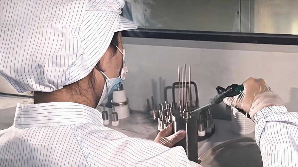
To achieve permanent hermetic sealing at the molecular level, a strict ceramic-to-metal brazing process must be applied:
High-purity ceramic → Mo-Mn metallization → Nickel plating → Controlled-atmosphere vacuum brazing
Ceramic Sintering Process
Densification
For vacuum feedthrough applications, high-purity alumina ceramics typically achieve a sintered density of 3.85–3.95 g/cm³, depending on purity grade and processing conditions.
This ensures high-density microstructure with minimal residual porosity, enabling extremely low gas permeation required for UHV applications.
Precision machining
After sintering, high-precision grinding and cutting are required. Critical tolerances must be controlled within ±0.02 mm.
Any minor deviation may cause uneven brazing filler flow during subsequent sealing processes.
Mo-Mn Metallization Process
Process
Micron-scale Mo-Mn paste is screen-printed onto the ceramic sealing surface and sintered in a wet hydrogen reducing atmosphere at 1350°C–1450°C.
Mo-Mn metallization forms a manganese-rich spinel interfacial layer (MnAl2O4), which enables stable metallurgical bonding between ceramic and metal components.
A detailed explanation of this interfacial bonding mechanism can be found in Mo-Mn metallization process for ceramic sealing systems.
Key control
The metallization layer thickness is strictly controlled within 12–25 μm. Based on long-term production experience, this range provides an optimal balance between bonding strength and long-term reliability.
Nickel Plating and Hydrogen Degassing
Nickel plating
A 3–5 μm nickel layer is electroplated onto the metallized surface to prevent oxidation of the Mo layer and significantly improve brazing wettability.
Hydrogen degassing
After electroplating, hydrogen removal heat treatment must be performed immediately (150–200°C for 2 hours).
This reduces absorbed or trapped hydrogen, preventing hydrogen embrittlement during subsequent processing and service life.
Vacuum Brazing Process
Assembly brazing
Components are precisely aligned and Ag-Cu eutectic brazing alloy (melting point ~780°C) is applied. The assembly is placed into a vacuum furnace and evacuated to below 5×10⁻³ to 10⁻⁴ Pa.
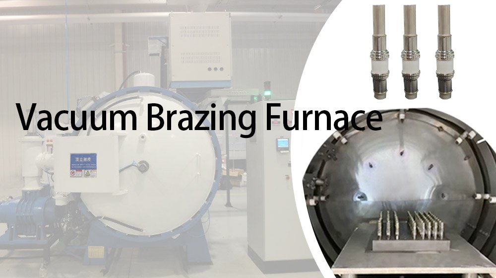
Capillary filling
Heating to 780–820°C with a holding time of 5–15 minutes allows the brazing alloy to fully wet and fill the joint gaps via capillary action.
Active Brazing Process
Principle
Active brazing provides an alternative ceramic-to-metal joining route using reactive elements such as Ti, Zr, or Hf.
At high temperatures, these elements chemically react with the ceramic surface to form an interfacial layer, enabling direct bonding without prior metallization.
However, in high-volume industrial production, Mo-Mn metallization combined with Ag-Cu brazing remains the dominant and more widely adopted process.
Selection guideline
In most industrial and mass-production vacuum feedthroughs, the conventional Mo-Mn metallization + Ag-Cu brazing route is preferred.
Active brazing is mainly used for aerospace-grade or special semiconductor customized components.
Manufacturing quality and interface integrity directly influence long-term vacuum reliability.
Failure Mechanisms and Reliability of Vacuum Feedthroughs
Long-term reliability of vacuum feedthroughs is influenced by thermal, mechanical, and vacuum-induced stresses. Common failure mechanisms include thermal fatigue, virtual leaks, and surface flashover.
A comprehensive analysis of ceramic-to-metal sealing failures is provided in ceramic-to-metal hermetic seal failure engineering guide.
Thermal Expansion Mismatch Mechanism
The CTE of alumina ceramics is significantly lower than that of metals such as stainless steel or copper.
During thermal cycling, this mismatch generates mechanical stress at the ceramic-to-metal interface, which can accumulate over repeated temperature changes and eventually lead to structural degradation.
A detailed explanation of thermal expansion compatibility in ceramic-to-metal sealing systems can be found in CTE matching in ceramic-to-metal seals, which provides engineering strategies for stress mitigation and material selection.
Thermal expansion mismatch between ceramics and metals generates cyclic stress. This stress can gradually lead to microcrack formation and eventual hermetic failure.
To mitigate this, a Kovar transition ring is introduced between the flange and the ceramic component. Its closely matched CTE effectively buffers thermal stress and ensures structural integrity.
Virtual Leak Formation Mechanism
Virtual leaks are caused by trapped geometrical volumes (such as blind holes), porous brazed interfaces, or slow gas desorption from enclosed cavities under vacuum conditions, which collectively degrade ultimate vacuum performance. Therefore, blind holes must be eliminated through structural design.
In addition, all finished products must undergo helium mass spectrometer leak testing to ensure hermetic performance.
Industry-standard leak testing methods and acceptance criteria for UHV systems are detailed in helium leak testing & hermetic standards.
Surface Flashover Mechanism
Surface flashover occurs when contamination such as moisture or metallic particles reduces surface resistivity, enabling charge accumulation and discharge initiation under high electric field stress along the ceramic surface.
To prevent this, high-voltage feedthroughs typically adopt one or more of the following strategies:
- Increasing ceramic surface rib or shed structures
- Applying insulating glaze coatings
- Increasing creepage distance to 3–5 mm per kV
These measures significantly improve surface insulation performance.
Understanding failure mechanisms is essential before defining selection criteria.
Vacuum Feedthrough Selection and Engineering Criteria
Six-Step Feedthrough Selection Method
1. Define transmission requirements
Determine whether the system requires high-voltage power, low-level signals, RF/microwave transmission, optical fiber, or conductive fluid transfer.
2. Determine electrical specifications
High voltage (>10 kV) applications require advanced ceramic insulation.
High current (>25 A) applications require thick copper conductors or multi-pin structures.
RF applications require impedance matching considerations.
3. Define vacuum level
Ultra-high vacuum applications require low outgassing materials and typically adopt ceramic-to-metal brazed structures with CF flange sealing.
4. Evaluate environmental conditions
Determine whether the system involves high-temperature baking (>250°C), thermal cycling, humidity, or chemical exposure.
5. Confirm flange interface
Ensure compatibility with CF, KF, or ISO standard interfaces in terms of dimensions and sealing requirements.
6. Balance lifetime and cost
Aerospace and medical systems prioritize reliability and thermal cycling resistance, while industrial applications focus on cost efficiency under acceptable leak-rate limits.
Engineering and Procurement Criteria
Reliable vacuum feedthrough selection also depends on strict engineering and supply chain evaluation.
- Material quality
Alumina ceramics should have high purity (typically ≥95%) and high sintered density to minimize outgassing in vacuum environments.
- Machining accuracy
Sealing interfaces must be controlled within tight tolerances (typically ±0.02 mm) to prevent virtual leakage risks.
- Manufacturing integration
Vertically integrated manufacturing helps ensure process stability across machining, metallization, and brazing steps.
Engineering FAQ: Feedthrough Reliability and Design
Q1: Why does leakage occur after several weeks of operation even if the product passed helium leak testing at shipment?
A1: Leakage after operation mainly comes from two mechanisms:
- Thermal expansion mismatch fatigue: Repeated thermal cycling between ceramic and metal can generate interfacial stress, leading to micro-crack formation over time.
- Virtual leaks from brazed joints: Micro-voids or trapped volumes in brazed interfaces may slowly release gas under high vacuum conditions.
These failure mechanisms are typically identified through combined thermal cycling and helium leak re-testing during reliability qualification.
Q2: How to determine whether high-voltage surface flashover is caused by moisture or metal dust?
A2: Moisture-induced flashover usually occurs during initial operation and can be significantly reduced or eliminated after proper vacuum baking.
If flashover persists after baking, it is more likely caused by conductive contamination such as metallic particles deposited on ceramic surfaces during plasma exposure or mechanical abrasion.
Q3: How to scientifically evaluate the service life of ceramic-to-metal sealed components?
A3: Service life is typically evaluated using accelerated reliability testing methods, including thermal cycling under defined temperature ranges such as –40°C to +125°C (or higher depending on application).
Test programs commonly include 300–500 thermal cycles, combined with vibration or mechanical shock testing when required.
Helium leak testing is performed at defined intervals to monitor hermetic degradation, and lifetime is estimated using accelerated aging models based on failure trends.
Engineering Summary
The reliability of vacuum feedthroughs determines the long-term performance of high-vacuum and ultra-high vacuum systems.
Achieving stable hermetic sealing requires coordinated control of material selection, interfacial bonding, and manufacturing processes.
In extreme environments such as thermal cycling and ultra-high vacuum, even small defects in materials or interfaces can lead to leakage, mechanical fatigue, or electrical failure over time.
Therefore, hermetic performance depends on a system-level engineering approach that integrates materials, sealing processes, and manufacturing control.
Engineering Support and Custom Solutions
We provide customized ceramic-to-metal sealing solutions for vacuum and ultra-high vacuum applications.
Our feedthrough solutions are designed for electrical insulation, thermal stability, and mechanical reliability under demanding operating conditions.
As a vertically integrated manufacturer, Jinghui Ceramics ensures full-process control from ceramic machining to metallization and vacuum brazing assembly.
For engineering support or custom design, please submit your drawings (STEP/CAD) for evaluation.