

Introduction
Ceramic setter plates may develop cracks during repeated heating and cooling, making thermal shock an important factor to consider. For alumina ceramic setter plates, setter plates used for electronic ceramic sintering, and other ceramic plates exposed to frequent thermal cycling, thermal shock can have a significant impact on service life.
So, how much ΔT is actually safe for ceramic setter plates?
There is no universal safe ΔT that applies to all ceramic setter plates. In water-quenching thermal shock tests, the critical ΔT of some alumina materials is approximately 200–250°C, while some silicon carbide materials can reach 450–500°C.
However, these test values cannot be directly used as the safe temperature difference for actual furnace operation. In real applications, thermal shock is also affected by heating and cooling rates, plate thickness, plate dimensions, furnace temperature uniformity, surface defects, and the number of thermal cycles.
This article starts by explaining the difference between ΔT and temperature gradient, then examines why ceramic setter plates develop thermal shock cracks, compares the thermal shock resistance of different ceramic materials, and finally summarizes the key factors that should be considered when evaluating thermal shock risk under actual operating conditions.
Understanding ΔT in Ceramic Setter Plate Thermal Shock
ΔT generally represents the difference between two temperatures. In a simple heating process, it can be expressed as:
ΔT = T₂ − T₁
where T₁ is the initial temperature and T₂ is the final temperature.
For example, if a ceramic setter plate is heated from room temperature, 25°C, to 500°C, the temperature change is:
ΔT = 500 − 25 = 475°C
However, when analyzing the thermal shock risk of a ceramic setter plate, it is not sufficient to consider only the furnace temperature change.
During rapid heating, the furnace temperature does not immediately transfer evenly throughout the entire setter plate. Because ceramic materials require time to conduct heat toward the interior, the surface of the setter plate may already be close to the target temperature, while the interior remains at a lower temperature.
Therefore, significant temperature differences may exist between different regions inside the setter plate at the same time. This temperature gradient, caused by different heating rates in different regions of the material, is an important source of thermal stress.
The following illustration shows how the surface and interior of a ceramic setter plate do not reach the same temperature simultaneously during rapid heating.
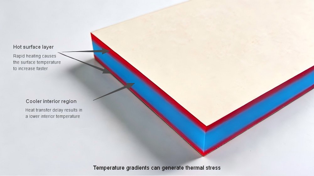
As shown in the illustration, the surface layer absorbs heat and heats up rapidly, while the interior remains at a lower temperature because heat transfer lags behind. The temperature difference between the surface and interior causes different regions of the material undergo different amounts of thermal expansion, generating internal stress.
Therefore, actual thermal shock risk depends on the temperature gradient formed inside the material and the resulting thermal stress, rather than simply on the magnitude of the furnace temperature change from one temperature to another.
Why Ceramic Setter Plates Develop Thermal Shock Cracks
When a ceramic setter plate undergoes rapid heating or cooling, different regions inside the material change temperature at different rates, resulting in a temperature gradient.
This temperature gradient generates thermal stress inside the material.
If the resulting thermal stress exceeds the material’s strength limit, cracks may initiate at internal defects, edge regions, or areas of stress concentration and gradually propagate during subsequent thermal cycles.
The failure process caused by thermal shock typically includes:
Temperature change → Temperature gradient formation → Thermal stress generation → Crack initiation → Crack propagation → Setter plate failure
For ceramic setter plates operating in high-temperature cyclic environments over long periods, repeated thermal stress may gradually reduce thermal cycling service life even if a single thermal cycle does not immediately cause fracture.
The following image shows a through-crack in a ceramic setter plate caused by thermal shock.
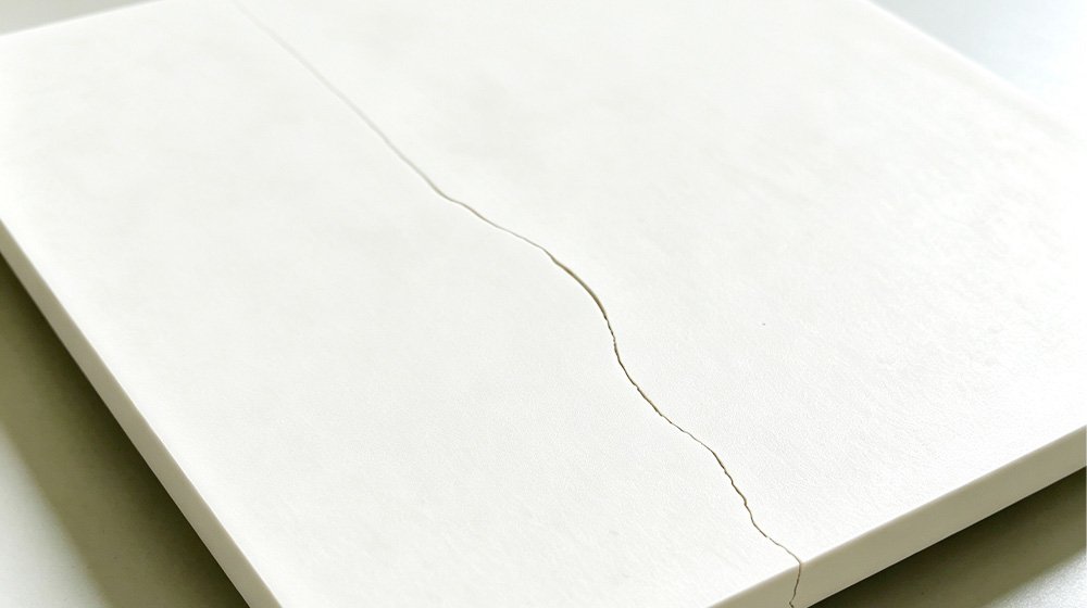
Cracks of this type generally indicate that significant internal damage has already developed. During subsequent heating and cooling cycles, the cracked area becomes a new stress concentration point, further increasing the risk of crack propagation and sudden fracture.
Therefore, when thermal shock cracks appear in a setter plate, it is important not to focus only on the crack itself. The underlying causes of thermal stress should also be analyzed, including heating and cooling rates, plate dimensions and thickness, material thermal properties, and the actual furnace temperature distribution.
For a detailed analysis of common alumina setter plate cracking causes and practical solutions, you can refer to our guide on why alumina setter plates crack.
Thermal Shock Resistance of Ceramic Materials
Different ceramic materials exhibit different levels of thermal shock resistance during rapid heating and cooling because of differences in thermal conductivity, coefficient of thermal expansion, strength, and microstructure.
Water-quenching thermal shock testing is a commonly used method for evaluating the thermal shock resistance of ceramic materials. In this test, a specimen is typically heated to a specified temperature and then rapidly cooled, for example by quenching it in room-temperature water. The material’s resistance to sudden temperature changes is then evaluated by observing changes in strength or the presence of cracks.
It is important to note that the critical temperature difference obtained from water-quenching thermal shock tests is mainly used to compare the thermal shock resistance of different materials. It cannot be directly equated with the safe temperature difference for an actual ceramic setter plate in a furnace.
In practical applications, the thermal shock experienced by a setter plate is also affected by plate dimensions, thickness, heating and cooling rates, temperature distribution inside the furnace, surface defects, and the number of thermal cycles.
The following table provides reference data for several common ceramic materials under water-quenching thermal shock test conditions. The data is intended for comparison between different materials.
| Material | Reference ΔT Range from Water-Quenching Thermal Shock Tests (°C) | Flexural Strength (MPa) | Thermal Conductivity (W/m·K) | CTE (10⁻⁶/K) |
| Mullite | 150–180 | ≥110 | 5 | 5.0–5.8 |
| 99% Alumina | 180–200 | ≥310 | 29 | 6.5–8.0 |
| 95% Alumina | 220–250 | ≥280 | 20–25 | 6.5–8.0 |
| ZTA (10% ZrO₂) | 320–380 | ≥450 | 20–25 | 7.5–8.5 |
| Reaction-Bonded Silicon Carbide | 350–400 | 250–350 | 120–150 | 4.0–5.0 |
| Yttria-Stabilized Zirconia | 400–450 | 900–1200 | 2–3 | 10.0–11.0 |
| Recrystallized Silicon Carbide | 450–500 | 300–400 | 150–180 | 4.5–5.5 |
| Silicon Nitride | 500–600 | 600–800 | 25–35 | 3.0–3.2 |
Note: The values in the table are reference ranges compiled from different publicly available technical sources and are intended for comparison between materials. Actual test results may vary depending on material composition, microstructure, specimen dimensions, test method, and test conditions. ASTM C1525 specifies a water-quenching test method for evaluating thermal shock resistance, but it does not define fixed thermal shock limits for different ceramic materials.
The data above leads to several important observations.
Thermal Conductivity and Thermal Shock
Thermal conductivity affects the ability of a material to transfer heat internally. During rapid heating and cooling, materials with higher thermal conductivity can transfer heat more quickly, helping reduce the temperature difference between different regions of the material and lowering the thermal stress caused by temperature gradients.
For example, silicon carbide generally has significantly higher thermal conductivity than alumina and therefore typically exhibits higher thermal shock resistance in water-quenching thermal shock tests. However, thermal conductivity is not the only factor determining thermal shock resistance.
Thermal Expansion and Thermal Strain
Materials expand or contract as their temperature changes. A lower coefficient of thermal expansion generally results in smaller dimensional changes under the same temperature change and therefore helps reduce thermal strain during thermal shock.
For example, silicon nitride has a relatively low coefficient of thermal expansion, which is one of the important factors contributing to its good thermal shock resistance.
Multiple Factors Determine Thermal Shock Resistance
Although thermal conductivity and coefficient of thermal expansion have important effects on thermal shock performance, actual thermal shock resistance also depends on multiple factors, including flexural strength, fracture toughness, microstructure, grain size, porosity, and defect conditions.
Therefore, a material’s suitability for high-temperature setter plates cannot be determined based on a single parameter alone.
Zirconia Has a Unique Toughening Mechanism
Zirconia has relatively low thermal conductivity and a relatively high coefficient of thermal expansion, yet some stabilized zirconia materials still exhibit good thermal shock resistance.
This is because zirconia may undergo a phase transformation from the tetragonal phase (t) to the monoclinic phase (m) during crack propagation, accompanied by volume expansion that helps inhibit crack propagation.
This transformation toughening mechanism is one of the important reasons why some zirconia materials have relatively high crack resistance.
Alumina Purity and Thermal Shock Resistance
The reference data in the table shows that the water-quenching thermal shock reference ΔT of 99% alumina is lower than that of 95% alumina.
This reference data indicates that the thermal shock resistance of alumina materials is not determined simply by alumina content.
In addition to purity, factors such as microstructure, porosity, grain size, sintering process, and strength level can also affect thermal shock performance.
Therefore, when selecting alumina setter plates, it is not appropriate to assume simply that “higher purity means better performance.” Actual thermal cycling conditions should also be considered in the overall evaluation.
Five Factors Affecting Ceramic Setter Plate Thermal Shock Risk
Even when setter plates are made from the same ceramic material and experience the same furnace temperature change, different plates may exhibit different levels of thermal shock resistance.
In practical applications, thermal shock risk is usually influenced by the combined effects of the following five factors.
Material Thermal Properties
Thermal conductivity affects the ability of heat to transfer through the material and therefore influences the formation of temperature gradients, while the coefficient of thermal expansion affects the dimensional changes that occur as the material temperature changes.
Under otherwise similar conditions, higher thermal conductivity generally helps reduce the temperature gradient formed during rapid heating and cooling, while a lower coefficient of thermal expansion generally helps reduce thermal strain.
Therefore, when evaluating the thermal shock resistance of a setter plate, it is not sufficient to consider only the material name or maximum operating temperature. Its specific thermal and mechanical properties should also be considered.
Heating and Cooling Rate
The faster the heating or cooling process, the more likely the material is to develop a large transient temperature gradient, increasing thermal stress and thermal shock risk.
Even if two setter plates experience the same temperature change range, different heating and cooling durations may result in significantly different thermal shock behavior.
Therefore, actual evaluation should consider the complete heating and cooling profile rather than only the initial temperature and maximum temperature.
Plate Thickness and Temperature Gradient
The thicker the plate, the longer it generally takes for heat to transfer from the surface to the interior. Under rapid heating and cooling conditions, thicker plates are more likely to develop significant temperature gradients through the thickness.
Therefore, setter plate thickness should not be determined solely by mechanical load-bearing requirements. Operating temperature, heating and cooling rates, plate dimensions, and thermal cycling conditions should also be considered.
For applications requiring rapid thermal cycling, “thicker” does not necessarily mean “more durable.”
Plate Size, Structure, and Furnace Temperature Uniformity
If a large setter plate is located in an area of the furnace with uneven temperature distribution, the center and edges may experience different temperature changes, increasing local thermal stress.
At the same time, geometric features such as holes, slots, and sharp corners can create local stress concentrations, making these areas more likely to become crack initiation points.
Therefore, large or structurally complex setter plates require particular attention to furnace temperature uniformity and local structural design. For more guidance on setter plate design, dimensions, and material selection, please refer to our alumina setter plate design guide.
Surface and Edge Defects: Crack Initiation Risks
Edge chipping, scratches, and microcracks can create local stress concentrations and may become starting points for crack initiation and propagation during thermal cycling.
For setter plates exposed to frequent thermal cycling, minor damage caused during handling, furnace loading, and cleaning should not be overlooked.
The actual thermal shock resistance of a setter plate depends not only on the material itself, but also on the condition of its surfaces and edges before and after use.
The Same ΔT Does Not Mean the Same Thermal Shock Risk
When evaluating the thermal shock risk of a ceramic setter plate, material thermal properties, heating and cooling rates, plate thickness, size and geometry, furnace temperature uniformity, and surface defects all need to be considered together.
For applications involving frequent thermal cycling, the number of cycles and crack accumulation effects should also be considered.
A setter plate may not fail during the first thermal shock event. Instead, existing microcracks may gradually propagate after multiple thermal cycles, eventually resulting in cracking.
Preventing Thermal Shock Cracking in Ceramic Setter Plates
If a setter plate develops cracks during thermal cycling, rather than simply upgrading the material grade, it is more important to investigate thermal shock risks from the perspectives of the temperature profile, plate design, furnace temperature uniformity, and surface condition.
Optimize Heating and Cooling Profiles
Avoid exposing the setter plate to a large temperature change within an extremely short period of time.
For thicker or larger setter plates, particular attention should be paid to the rate of temperature change during heating and cooling. An appropriate temperature profile should be developed based on the material, plate dimensions, and thickness.
For a specific product, suitable heating and cooling conditions should be verified through the actual furnace temperature profile and thermal cycling tests rather than directly applying a fixed heating or cooling rate.
Improve Furnace Temperature Uniformity
Large setter plates should, as far as possible, be kept away from the furnace door, furnace walls, or other areas with significant temperature fluctuations, and the different areas of the plate should ideally remain in a relatively uniform temperature environment.
If there is a persistent temperature difference between the center and edges of the setter plate, the actual thermal shock experienced by the plate may differ even when the furnace temperature setpoint is the same.
Optimize Plate Thickness and Structure
Setter plates that are too thick are more likely to develop significant internal temperature gradients during rapid heating and cooling. Therefore, plate thickness should be balanced between mechanical load-bearing requirements and thermal shock requirements.
At the same time, appropriate corner-radius or chamfer designs at locations such as holes, slots, and edges where stress concentrations may occur can help reduce local stress concentration.
Minimize Edge and Surface Damage
Impacts, dropping, and localized mechanical shocks should be avoided during handling and furnace loading.
Before use, the edges should be checked for chips, scratches, or visible cracks, as these defects may create stress concentrations and further propagate during subsequent thermal cycles.
For setter plates that require long-term repeated use, establishing regular inspection standards and replacement rules can also help reduce the risk of sudden failure caused by accumulated defects.
Evaluate Material and Process Compatibility
If the process involves heating from room temperature to 800°C in 10 minutes, you cannot determine whether the setter plate is safe simply by comparing this condition with the critical ΔT obtained from the material’s water-quenching thermal shock test.
The actual evaluation should consider the heating and cooling profiles, plate thickness and dimensions, material thermal conductivity and coefficient of thermal expansion, temperature distribution inside the furnace, the surface and edge conditions of the setter plate, and the number of thermal cycles.
For new materials, dimensions, or structures, it is best to verify their suitability through actual thermal cycling tests.
Thermal Shock Crack Investigation Example
Suppose an alumina setter plate is used in a thermal cycling process at approximately 800°C and develops edge cracks after a period of use.
In this situation, it should not be immediately concluded that the material has insufficient thermal shock resistance. Instead, the actual heating and cooling profile, furnace temperature uniformity, condition of the plate edges, and whether the plate thickness and structure are suitable for the application should first be checked.
If a significant temperature difference is also found between the center and edges of the furnace, while the setter plate edges show impact damage, these factors may jointly increase local thermal stress and the risk of crack propagation.
Therefore, compared with simply replacing the material, first optimizing the furnace temperature distribution, improving handling methods, and reassessing the plate design may provide a more targeted solution.
Core Principle: Identify the primary risk factors in the actual thermal cycling process first, then decide whether to optimize the process, adjust the plate design, or change the material.
Why There Is No Fixed Safe ΔT
The critical ΔT obtained from water-quenching thermal shock tests can be used to compare the thermal shock resistance of different ceramic materials, but it cannot be directly equated with the maximum temperature difference that an actual setter plate can withstand inside a furnace.
Under actual operating conditions, the thermal shock risk of a setter plate is also affected by plate dimensions, thickness, heating and cooling rates, furnace temperature uniformity, surface defects, and the number of thermal cycles.
Thermal Shock Risk Assessment Logic Chain
In practical applications, evaluating whether a ceramic setter plate is suitable for a specific thermal cycling condition generally requires analyzing the complete process from input conditions to eventual failure risk.
The following logic chain shows the relationship between material properties, plate design, and thermal cycling service life.
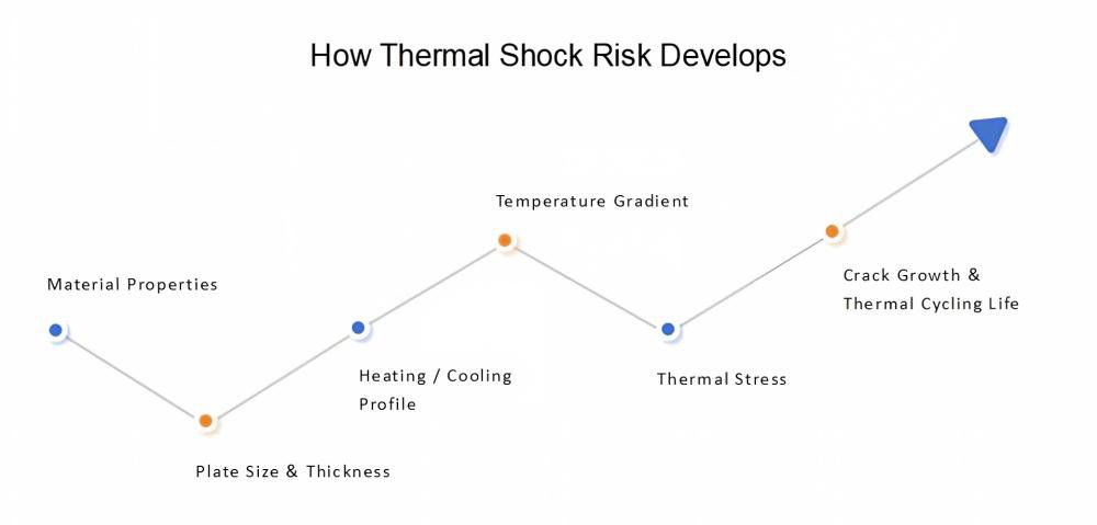
This logic chain shows that thermal shock risk is not determined by a single material parameter, but by the combined effects of multiple engineering factors.
For example, even if two alumina setter plates undergo the same furnace temperature change, their internal temperature gradients and thermal stress levels may be significantly different if their plate thickness, heating rate, or furnace temperature uniformity differs.
In other words, what is safe is not a single fixed ΔT, but a complete set of properly matched material, plate design, and thermal process conditions.
If a setter plate has already developed cracks, do not focus only on ΔT. It is more useful to check:
- Did the crack start from the edge or the plate surface?
- Did the crack appear during heating or cooling?
- Does the crack always occur in the same location?
- How many thermal cycles has the setter plate experienced?
- Are the plate thickness and dimensions suitable for the current thermal cycling conditions?
- Is there significant temperature non-uniformity inside the furnace?
- Are there impacts, edge chips, or scratches on the edges?
- Does the product weight or placement method create local mechanical constraints?
These details are often more helpful than simply knowing a single “ΔT value” when determining the actual cause of thermal shock cracking.
Evaluating Ceramic Setter Plate Thermal Shock Risk
ΔT alone cannot tell you whether a ceramic setter plate is safe.
The critical ΔT from water-quenching thermal shock tests can help compare the thermal shock resistance of different ceramic materials, but actual furnace operating conditions are much more complex.
The thermal shock risk of a setter plate depends on factors such as material thermal properties, plate dimensions and thickness, heating and cooling rates, furnace temperature uniformity, surface and edge conditions, and the number of thermal cycles.
The same ΔT may produce completely different results with different materials, different plates, and different thermal cycling conditions.
Therefore, when selecting a ceramic setter plate, do not ask only, “How much ΔT can this material withstand?” Instead, further evaluate whether the material matches the actual furnace temperature profile, whether the plate design is suitable for thermal cycling, and whether the actual operating conditions have been validated.
Ceramic Setter Plate Thermal Shock FAQ
Q1. What is a safe ΔT for an alumina ceramic setter plate?
A1: There is no universal safe ΔT that applies to all alumina ceramic setter plates.
The critical thermal shock temperature difference obtained from material testing can only serve as a reference for comparing thermal shock resistance. Actual operating conditions also need to be evaluated based on factors such as plate dimensions, thickness, heating and cooling rates, furnace temperature uniformity, and the number of thermal cycles.
Q2. Why do alumina setter plates have different service lives?
A2: Material name and alumina content alone cannot fully represent actual performance.
Material factors such as composition, microstructure, sintering process, density, and porosity, as well as plate dimensions, machining accuracy, surface condition, and edge defects, can all affect actual thermal shock resistance.
Q3. Can a ceramic setter plate still be used after cracking?
A3: Continued use is generally not recommended, especially under high-temperature, repeated thermal cycling, or high-load conditions.
A crack can become a stress concentration point and a starting point for further crack propagation, increasing the risk of sudden fracture or fragment detachment during thermal cycling.
For a setter plate that has already developed cracks, its condition should be evaluated based on the crack location, size, and specific application requirements, and the plate should be replaced when necessary.
Q4. How should I select a ceramic setter plate for thermal cycling?
A4: First determine the actual operating conditions, including operating temperature, heating and cooling rates, number of thermal cycles, plate dimensions and thickness, furnace atmosphere, and contact materials.
Then consider the material’s thermal conductivity, coefficient of thermal expansion, strength, chemical stability, and cost.
For applications involving frequent thermal cycling, selection should not be based only on the material name or maximum operating temperature. The actual furnace temperature profile and product structure should also be evaluated, and sample testing should be conducted when necessary.
Need Help Selecting an Alumina Ceramic Setter Plate?
If you need help selecting an alumina ceramic setter plate or evaluating thermal shock issues, we can help assess whether the material, plate design, and thermal cycling conditions are appropriately matched.
Share your operating temperature, heating and cooling profile, plate dimensions, and application requirements with us.