

Introduction
Thin-wall ceramic components are increasingly used in semiconductor equipment, automotive sensors, medical devices, fluid control systems, precision machinery, and electronic packaging. Their combination of wear resistance, electrical insulation, corrosion resistance, and dimensional stability makes them attractive alternatives to metals in demanding applications.
However, manufacturing thin-wall ceramic components is significantly more challenging than machining conventional ceramic parts. As wall thickness decreases, structural rigidity is reduced, while sensitivity to grinding forces, residual stress, fixturing, and dimensional variation increases. Defects such as edge chipping, warpage, hidden microcracks, or assembly fractures are often related to interactions among multiple manufacturing stages rather than to a single machining operation.
For this reason, successful thin-wall ceramic manufacturing depends on coordinated engineering decisions throughout the production process—from component design and material selection to forming, sintering, precision grinding, inspection, and final assembly. Improving one process alone is rarely sufficient to ensure consistent product quality.
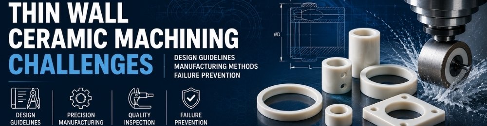
This article summarizes the major engineering challenges, practical design recommendations, manufacturing methods, inspection strategies, and failure analysis considerations involved in producing precision thin-wall ceramic components.
Why Thin-Wall Ceramic Components Are Challenging
Unlike metallic materials, engineering ceramics exhibit high compressive strength but limited tolerance to tensile stress and virtually no plastic deformation. This means that local stress concentrations generated during machining cannot be relieved through permanent deformation as they can in metals.
As wall thickness decreases, even small machining forces or fixture loads may cause localized deformation or stress concentration. Although the component may appear dimensionally acceptable after machining, microscopic damage introduced during grinding can propagate later during transportation, assembly, thermal cycling, or service.
Therefore, thin-wall ceramic machining should not be viewed simply as a precision grinding process. It is better understood as a manufacturing system in which component geometry, material properties, process capability, inspection methods, and assembly conditions all influence the final performance.
Engineering Insight
Thin-wall ceramic reliability is determined by the interaction of design, manufacturing, inspection, and assembly rather than by machining accuracy alone.
What Is Considered a Thin-Wall Ceramic Component?
There is currently no universally accepted international standard defining a thin-wall ceramic component. In engineering practice, manufacturability is evaluated by considering wall thickness together with overall geometry, unsupported span, aspect ratio, material properties, and application requirements.
For example, a wall thickness of 1 mm may be relatively straightforward to manufacture on a small ceramic sleeve, while the same thickness on a large-diameter ring or plate may present significant challenges due to reduced structural rigidity and increased distortion during sintering.
Consequently, experienced manufacturers evaluate thin-wall designs from a system perspective rather than relying on wall thickness alone.
Engineering Factors That Determine Machining Difficulty
Wall thickness is only one factor influencing machining difficulty. In practice, engineers evaluate multiple structural and manufacturing variables before selecting machining strategies.
The following factors generally have the greatest influence on manufacturing stability:
| Engineering Factor | Influence on Machining |
|---|---|
| Wall Thickness | Structural rigidity |
| Component Geometry | Stress distribution |
| Unsupported Length | Vibration tendency |
| Material Type | Grinding behavior |
| Sintering Shrinkage | Dimensional stability |
| Grinding Strategy | Surface integrity |
| Fixture Design | Load distribution |
| Inspection Capability | Quality verification |
Instead of optimizing one parameter, manufacturers usually seek to balance these factors to improve both product quality and production consistency.
Thin-wall ceramic machining is fundamentally different from conventional ceramic machining. Manufacturing success depends on system-level engineering decisions rather than machining precision alone. Understanding how geometry, materials, process control, and inspection interact provides the foundation for designing reliable ceramic components and improving production consistency.
Why Thin Wall Ceramic Parts Are Difficult to Manufacture
Unlike metals, engineering ceramics cannot accommodate machining errors through plastic deformation. Once local stress exceeds the material’s fracture strength, cracks may initiate suddenly with little warning. As wall thickness decreases, structural rigidity is reduced, making the component increasingly sensitive to grinding forces, thermal gradients, fixturing pressure, and residual stress.
For this reason, thin-wall ceramic machining is not simply a matter of using higher-precision equipment. Successful manufacturing depends on controlling the entire process—from material selection and green-body forming to sintering, precision grinding, inspection, and handling.
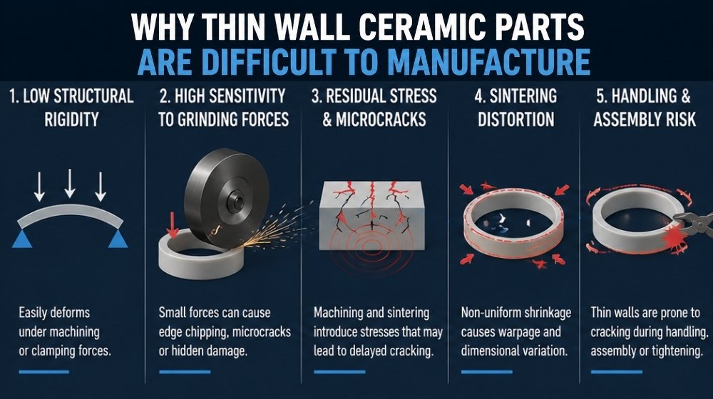
Many manufacturing defects originate from the interaction of multiple process variables rather than from a single machining step.
Challenge 1 — Low Structural Rigidity
As wall thickness decreases, the component becomes less capable of resisting machining forces. Even relatively small grinding loads may cause local deflection, vibration, or stress concentration.
Unlike metallic materials, ceramics cannot absorb this energy through elastic-plastic deformation. Instead, excessive local stress may produce edge chipping or initiate microscopic cracks that remain invisible until later inspection or assembly.
Structural rigidity therefore depends not only on wall thickness but also on component diameter, unsupported length, rib geometry, and fixture design.
Engineering Insight
Thin-wall machining difficulty is determined by overall geometry, not by wall thickness alone.
Challenge 2 — Grinding Force Control
Diamond grinding is the most common finishing process for advanced ceramics. During machining, excessive grinding force may introduce localized tensile stress, resulting in edge breakout, surface damage, or subsurface cracking.
Grinding parameters—including wheel speed, feed rate, depth of cut, coolant delivery, and wheel condition—must remain stable throughout production.
Reducing grinding force is generally more effective than simply increasing machine rigidity.
Typical Grinding Damage
| Grinding Issue | Possible Result |
|---|---|
| Excessive Grinding Force | Edge Chipping |
| High Local Temperature | Residual Stress |
| Large Depth of Cut | Surface Crack |
| Poor Coolant Flow | Thermal Damage |
| Worn Grinding Wheel | Poor Surface Finish |
Challenge 3 — Heat Generation During Machining
Although engineering ceramics generally possess excellent high-temperature resistance, localized heat generated during grinding can still influence machining quality.
Rapid temperature changes may introduce thermal gradients near the machined surface. When combined with mechanical stress, these gradients can increase the likelihood of residual stress or microscopic cracking.
Effective coolant delivery and optimized grinding parameters are therefore essential for maintaining machining stability.
Engineering Insight
Heat damage is usually localized rather than affecting the entire component.
Challenge 4 — Residual Stress
Residual stress is one of the most overlooked causes of delayed ceramic failure.
Residual stresses may originate from powder compaction, sintering shrinkage, grinding, polishing, or uneven cooling. Although these stresses may not produce immediate cracking, they can reduce the component’s safety margin during transportation, assembly, or service.
For thin-wall components, minimizing residual stress is often more important than achieving the lowest possible surface roughness.
Challenge 5 — Edge Chipping
Edge chipping is one of the most frequently observed defects in thin-wall ceramic machining.
Because stress naturally concentrates at sharp edges, corners, holes, and slots, these regions are more susceptible to material removal beyond the intended geometry.
Proper chamfer design, optimized grinding paths, and reduced cutting loads can significantly decrease the risk of edge breakout.
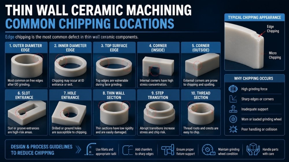
Typical Chipping Locations
- Outside Edge
- Hole Entrance
- Slot Corner
- Thin Rib
- Sharp Corner
Engineering Summary
The first five challenges share a common characteristic: they are strongly interconnected.
For example, excessive grinding force increases heat generation, which may create residual stress. Residual stress, combined with low structural rigidity, can eventually lead to edge chipping or delayed cracking.
Successful thin-wall ceramic machining therefore depends on process control rather than on any single machining parameter.
Challenge 6 — Warpage and Distortion
Thin-wall ceramic components are particularly sensitive to dimensional distortion during sintering.
Unlike metals, ceramic components undergo significant shrinkage during densification. Although the shrinkage is generally predictable under controlled conditions, variations in wall thickness, unsupported geometry, temperature distribution, or green-body density may cause uneven shrinkage.
Typical deformation includes:
- Warpage
- Bowing
- Ovality
- Flatness deviation
- Twisting
These defects may remain within visual tolerance but still prevent proper assembly or sealing.
For complex geometries, warpage control should begin during the design stage rather than after machining.
Engineering Insight
Geometry usually has a greater influence on warpage than overall component size.
Challenge 7 — Dimensional Accuracy
Achieving dimensional consistency becomes increasingly difficult as wall thickness decreases.
A dimensional deviation that is acceptable on a thick component may represent a significant percentage of the wall thickness in a thin-wall design.
Engineers therefore evaluate not only dimensional tolerance but also:
- Roundness
- Flatness
- Parallelism
- Wall thickness variation
- Surface profile
Process capability is determined through the entire manufacturing route rather than through final grinding alone.
Engineering Insight
Dimensional stability depends on manufacturing consistency rather than machining precision alone.
Challenge 8 — Fixturing Design
Fixture design is often underestimated in ceramic machining.
A fixture that performs well for stainless steel may be unsuitable for ceramics because ceramic materials cannot tolerate concentrated clamping forces.
Excessive clamping pressure may introduce localized tensile stress, while insufficient support may allow vibration during grinding.
Effective fixturing seeks to distribute machining loads evenly across the component while minimizing deformation.
For thin-wall parts, fixture design is often optimized together with the machining process rather than treated as a separate task.
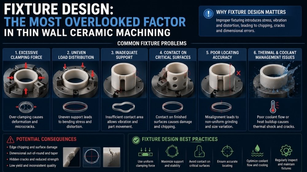
Typical Fixturing Problems
| Problem | Possible Result |
|---|---|
| Excessive Clamping Force | Crack Initiation |
| Insufficient Support | Vibration |
| Uneven Contact | Local Stress |
| Poor Alignment | Dimensional Error |
| Fixture Wear | Repeatability Reduction |
Challenge 9 — Inspection Challenges
Inspection of thin-wall ceramic parts presents challenges beyond dimensional measurement.
Because ceramic components are brittle, excessive measuring force may damage delicate features or introduce unnecessary stress.
Inspection commonly combines multiple techniques, depending on geometry and quality requirements, such as:
- Optical measurement
- Coordinate Measuring Machine (CMM)
- Vision inspection
- Surface roughness testing
- Microscopic crack inspection
For critical applications, dimensional inspection alone is insufficient. Surface integrity and hidden defects should also be evaluated when appropriate.
Engineering Insight
Quality is verified through multiple inspection methods rather than by dimensional measurement alone.
Challenge 10 — Manufacturing Yield
Manufacturing yield is one of the most important economic considerations for thin-wall ceramic components.
Compared with conventional ceramic parts, thin-wall geometries generally experience higher risks during forming, sintering, machining, inspection, handling, and transportation.
Yield therefore depends not only on machining capability but also on process consistency throughout production.
Rather than focusing on individual processing steps, experienced manufacturers typically improve yield by controlling the complete manufacturing system.
Factors Affecting Manufacturing Yield
| Process Stage | Typical Risk |
|---|---|
| Powder Processing | Density Variation |
| Forming | Green Crack |
| Sintering | Warpage |
| Grinding | Edge Chipping |
| Inspection | Hidden Defect Detection |
| Packaging | Mechanical Damage |
Engineering Summary
The ten challenges discussed above demonstrate that thin-wall ceramic machining is a system-level manufacturing process rather than a single machining operation.
Component performance is influenced by material selection, structural design, forming quality, sintering consistency, machining strategy, inspection capability, and process control.
Manufacturing success therefore depends on minimizing risk throughout the production process instead of optimizing only one individual step.
Choosing the Right Ceramic Material
Selecting a ceramic material for thin-wall components involves more than comparing mechanical properties. The material must also match the manufacturing process, component geometry, service environment, and cost target.
No single ceramic material is ideal for every application. Instead, engineers balance fracture resistance, machining difficulty, dimensional stability, thermal performance, and manufacturing consistency according to the product’s functional requirements.
For example, an alumina sensor housing and a silicon nitride bearing cage may both be thin-wall ceramic parts, but their design priorities are fundamentally different.
Material Comparison for Thin-Wall Machining
| Material | Machining Difficulty | Typical Advantages | Engineering Considerations |
|---|---|---|---|
| Alumina (Al₂O₃) | Medium | Good dimensional stability, cost-effective | Edge chipping should be controlled |
| Zirconia (ZrO₂) | Medium | Higher fracture toughness | Tool wear and thermal effects require attention |
| Silicon Nitride (Si₃N₄) | High | Excellent mechanical strength | More demanding grinding process |
| Silicon Carbide (SiC) | Very High | Outstanding wear resistance | Brittle removal mechanism increases machining difficulty |
| Aluminum Nitride (AlN) | High | High thermal conductivity | Moisture control and thermal management during processing are important |
Engineering Insight
Material selection should be based on application requirements rather than material popularity.
Design Guidelines for Thin-Wall Ceramic Components
Many machining problems originate during the design stage rather than during manufacturing.
A geometry that appears easy to manufacture in metal may become difficult or uneconomical when produced from engineering ceramics.
Designing for manufacturability (DFM) helps reduce machining risks while improving production consistency.
Recommended Design Practices
1. Maintain Uniform Wall Thickness
Large variations in wall thickness may result in uneven shrinkage during sintering, increasing the likelihood of warpage and internal stress.
2. Avoid Sharp Internal Corners
Sharp corners concentrate stress and increase the probability of crack initiation during machining and assembly. Rounded transitions generally improve manufacturability.
3. Use Chamfers or Small Radii
Chamfers help protect vulnerable edges during grinding, handling, and assembly while reducing the risk of edge chipping.
4. Minimize Deep and Narrow Slots
Deep slots reduce local stiffness and increase grinding difficulty. Wider openings with gradual transitions are generally easier to manufacture.
5. Keep Holes Away from Free Edges
Small edge distances may create stress concentration during machining or assembly. Additional material around holes usually improves reliability.
6. Avoid Long Unsupported Thin Sections
Long, slender features are more susceptible to vibration and deformation during grinding.
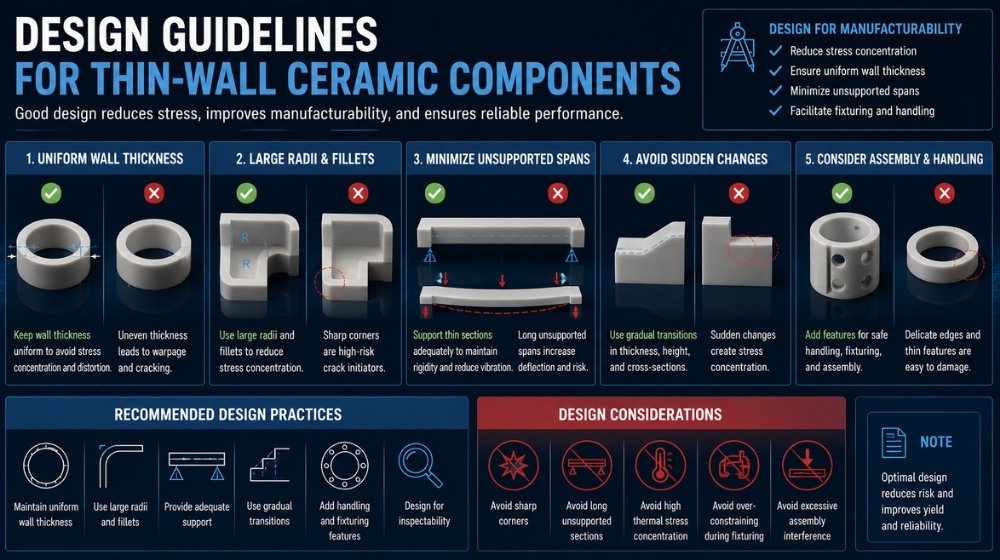
Typical DFM Checklist
| Design Item | Recommendation |
|---|---|
| Wall Thickness | Keep as uniform as practical |
| Internal Corners | Add radii where possible |
| Chamfers | Protect exposed edges |
| Slot Geometry | Avoid excessive depth |
| Hole Position | Maintain adequate edge distance |
| Support Features | Increase rigidity where necessary |
Machining Technologies for Thin-Wall Ceramics
Selecting the appropriate machining process is as important as selecting the ceramic material itself.
Each machining technology has different advantages, limitations, achievable tolerances, and suitable geometries. In many production environments, manufacturers combine several machining methods to obtain the required dimensional accuracy and surface quality.
Instead of relying on a single process, successful thin-wall ceramic manufacturing often follows a hybrid machining strategy.
Comparison of Common Machining Technologies
| Machining Method | Typical Application | Advantages | Limitations |
|---|---|---|---|
| Diamond Grinding | Precision dimensions and sealing surfaces | High accuracy and good surface finish | Slower material removal |
| Green Machining | Complex pre-sinter geometry | Reduces post-sinter machining | Limited to green bodies |
| Laser Machining | Small holes and micro features | High precision without mechanical contact | Heat-affected zone requires evaluation |
| Ultrasonic Machining | Fragile and complex geometries | Lower machining force | Lower productivity for large volumes |
| Lapping | Flat sealing surfaces | Excellent flatness | Material removal rate is low |
| Polishing | Optical or precision surfaces | Improves surface finish | Additional processing time |
Engineering Insight
No machining process is universally superior.
The optimal manufacturing route depends on component geometry, dimensional tolerance, surface finish requirements, production volume, and cost objectives.
Diamond Grinding — The Primary Finishing Process
Diamond grinding remains the primary finishing process for advanced ceramic components after sintering.
It provides excellent dimensional accuracy and surface integrity while maintaining the hardness advantages of ceramic materials.
However, grinding conditions must be carefully controlled because excessive grinding force or thermal loading may introduce subsurface damage that is difficult to detect visually.
Typical process variables include:
- Wheel specification
- Grinding speed
- Feed rate
- Depth of cut
- Coolant delivery
- Wheel dressing condition
Stable process control generally contributes more to manufacturing consistency than simply increasing machine precision.
Green Machining — Reducing Post-Sinter Machining
Green machining removes material before sintering, when the ceramic body is still relatively soft.
Compared with machining fully sintered ceramics, green machining generally requires lower cutting forces and improves machining efficiency.
However, green bodies possess limited mechanical strength. Improper handling or aggressive machining may still result in cracking or dimensional distortion.
Green machining is therefore most effective when integrated into the overall manufacturing plan rather than treated as an independent process.
Quality Inspection for Thin-Wall Ceramic Parts
Inspection does not simply verify dimensions—it confirms whether the manufacturing process has produced a component capable of meeting engineering requirements.
Depending on the application, inspection may include dimensional verification, surface quality assessment, geometric measurement, and defect evaluation.
Critical components often require inspection throughout production rather than only after machining.
Common Inspection Methods
| Inspection Method | Primary Purpose |
|---|---|
| Optical Measurement | Edge and geometry inspection |
| Coordinate Measuring Machine (CMM) | Precision dimensional measurement |
| Surface Roughness Tester | Surface finish evaluation |
| Optical Microscope | Edge chipping and microcracks |
| Vision Inspection | Automated appearance inspection |
| Flatness Measurement | Sealing surface verification |
Engineering Insight
Inspection should verify both dimensional accuracy and surface integrity, particularly for thin-wall components used in demanding applications.
Typical Applications of Thin-Wall Ceramic Components
Thin-wall ceramic components are increasingly used in industries requiring high precision, wear resistance, thermal stability, electrical insulation, or chemical resistance.
Their lightweight structures and dimensional stability make them suitable for applications where conventional metallic materials may experience wear, corrosion, or electrical limitations.
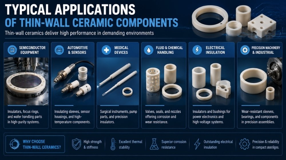
The specific material and geometry are selected according to the functional requirements of each application.
Typical Industrial Applications
| Industry | Typical Thin-Wall Ceramic Components |
|---|---|
| Semiconductor | Wafer handling parts, insulating rings |
| Automotive | Sensor housings, insulating components |
| Medical Devices | Precision sleeves, guide components |
| Electronics | Insulating spacers, ceramic carriers |
| Fluid Control | Valve seats, sealing rings |
| Textile Machinery | Yarn guides, ceramic eyelets |
| Chemical Processing | Corrosion-resistant liners and sleeves |
| Precision Machinery | Wear-resistant guide components |
Engineering Summary
Successful thin-wall ceramic manufacturing depends on selecting the appropriate combination of machining technologies rather than relying on a single process.
Inspection plays an equally important role by confirming both dimensional accuracy and structural integrity throughout production.
When supported by proper design and manufacturing control, thin-wall ceramic components can provide excellent performance in demanding industrial applications.
OEM Manufacturing Capability
Producing thin-wall ceramic components consistently requires more than advanced machining equipment.
OEM capability should be evaluated across the entire manufacturing process, including material preparation, forming, sintering, machining, inspection, and quality management.
A supplier capable of controlling process consistency is generally more valuable than one focusing only on dimensional tolerance.
OEM Evaluation Checklist
| Capability | Why It Matters |
|---|---|
| Material Consistency | Stable sintering behavior |
| Forming Process | Uniform green density |
| Precision Grinding | Final dimensional accuracy |
| Surface Finishing | Functional performance |
| Inspection Capability | Product consistency |
| Process Traceability | Quality assurance |
| Engineering Support | DFM optimization |
| Production Capacity | Stable supply |
Engineering Case Studies
Case Study 1 — Semiconductor Wafer Support Ring
A semiconductor handling system required a thin-wall alumina support ring with tight dimensional stability. Early prototypes experienced edge chipping during post-sinter grinding. After optimizing edge geometry, grinding parameters, and fixture support, manufacturing consistency improved without changing the ceramic material.
Case Study 2 — Automotive Sensor Housing
A ceramic sensor housing required thin walls to reduce weight while maintaining electrical insulation. Design optimization focused on maintaining uniform wall thickness and avoiding sharp transitions, helping improve dimensional consistency during sintering.
Case Study 3 — Textile Ceramic Guide
A thin-wall alumina yarn guide experienced occasional breakage during assembly. Investigation showed that assembly alignment rather than material quality was the primary contributor. Updating the fixture and installation procedure significantly reduced failures.
Case Study 4 — Precision Fluid Control Sleeve
A ceramic sleeve used in a precision fluid control system required both dimensional accuracy and corrosion resistance. Combining green machining with limited post-sinter grinding reduced machining time while maintaining the required geometry.
Engineering Summary
Failure prevention begins long before the machining stage.
Appropriate design, stable manufacturing processes, effective inspection, and correct assembly practices work together to improve the reliability of thin-wall ceramic components. Successful OEM manufacturing depends on process control across the entire production chain rather than on any single operation.
Engineering Myths About Thin-Wall Ceramic Machining
Myth 1 — Thicker Walls Always Improve Reliability
Increasing wall thickness does not automatically improve component reliability.
While thicker sections generally provide higher structural rigidity, abrupt wall-thickness transitions may introduce uneven sintering shrinkage, residual stress, and dimensional distortion. In many applications, a well-balanced wall design provides better manufacturing consistency than simply adding more material.
Myth 2 — Higher Precision Machines Solve Every Machining Problem
Machine accuracy is only one factor affecting machining quality.
Grinding parameters, fixture design, wheel condition, coolant control, material consistency, and operator experience all influence the final result. Even highly accurate CNC equipment cannot compensate for poor product design or unstable manufacturing processes.
Myth 3 — Cracks Always Originate During Machining
Not every crack forms during machining.
Some microscopic defects may originate during forming or sintering and remain undetected until later grinding, transportation, or assembly. Effective root-cause analysis should evaluate the complete manufacturing history instead of focusing on one production step.
Myth 4 — Lower Cost Means Better Manufacturing Efficiency
A lower purchase price does not necessarily indicate a lower manufacturing cost.
Thin-wall ceramic components require stable production processes, specialized inspection, and careful handling. Poor manufacturing consistency may increase scrap rates, maintenance costs, and production interruptions. Long-term value is often determined by process capability rather than initial price.
Conclusion
Thin-wall ceramic machining is one of the most demanding manufacturing processes in advanced ceramics.
Unlike conventional ceramic components, thin-wall structures require close coordination between material selection, product design, sintering control, precision grinding, inspection, and assembly. Success depends on understanding how these manufacturing stages interact rather than optimizing any single process alone.
For engineers and OEM buyers, selecting an experienced manufacturing partner is often just as important as selecting the ceramic material itself. Stable process capability, consistent quality control, and engineering support can significantly improve production reliability while reducing long-term manufacturing risk.
As industrial equipment continues to demand lighter, smaller, and higher-precision ceramic components, thin-wall ceramic machining will remain an important capability across semiconductor, automotive, medical, electronics, and precision machinery industries.
Frequently Asked Questions (FAQ)
1. What is considered a thin-wall ceramic component?
There is no universal industry standard defining a thin-wall ceramic component. In engineering practice, wall thickness is evaluated together with overall geometry, aspect ratio, unsupported length, and application requirements. A 1 mm wall may be relatively easy to manufacture on a small part but extremely challenging on a large-diameter component. Therefore, manufacturability depends on the complete structural design rather than wall thickness alone.
2. Why do thin-wall ceramic parts crack during machining?
Machining cracks usually result from the combined effects of grinding force, residual stress, fixture design, and local geometry. Excessive cutting loads or poor support may generate microscopic damage that is not immediately visible. Optimizing process parameters, improving edge geometry, and maintaining stable manufacturing conditions are generally more effective than increasing machine accuracy alone.
3. Which ceramic material is best for thin-wall machining?
There is no single “best” ceramic material for every thin-wall application. Alumina is widely used because of its balance between cost and manufacturability, zirconia offers higher fracture toughness, silicon nitride performs well in demanding mechanical environments, and aluminum nitride is selected where thermal conductivity is critical. Material selection should always be based on functional requirements rather than material popularity.
4. How can edge chipping be minimized during machining?
Reducing edge chipping requires a combination of proper component design and controlled manufacturing processes. Rounded edges, appropriate chamfers, optimized grinding parameters, suitable fixture support, and regular wheel maintenance all contribute to reducing local stress concentrations. Quality inspection should also verify edge integrity before components proceed to assembly.
5. How should OEM buyers evaluate a thin-wall ceramic supplier?
OEM buyers should evaluate more than machining capability alone. Important considerations include material consistency, forming technology, sintering control, dimensional inspection, quality management, engineering support, process traceability, and production capacity. A supplier capable of maintaining stable manufacturing processes often delivers better long-term reliability than one competing primarily on price.
6. Can thin-wall ceramic components replace metal parts?
In many applications, yes—but not universally. Thin-wall ceramics provide advantages such as wear resistance, electrical insulation, corrosion resistance, and dimensional stability. However, components subjected to severe impact, large deformation, or frequent mechanical shock may still be better served by metallic materials. Material selection should be based on the application’s operating conditions and engineering requirements rather than on material type alone.