
Introduction
In the field of precision ceramics manufacturing, the fracture of ceramic components often triggers a chain reaction of problems, including production line shutdowns, order delivery delays, and soaring repair costs. Many engineers’ first reaction is usually, “Ceramic materials are too brittle and unreliable.”
However, based on our years of experience in ceramic failure analysis, most failures do not stem from defects in the material itself, but rather from the combined effects of multiple factors, including design, material selection, machining processes, and the operating environment.
This article will systematically analyze the main causes of ceramic failure based on typical cases and engineering experience, and help engineers identify potential risks and optimize design and manufacturing strategies.
Ceramic Failure Insights
1. In most cases, ceramic fracture is not due to the material itself. Over 80% of failure cases show that the root cause of ceramic failure lies in oversights in the design, machining, and selection stages.
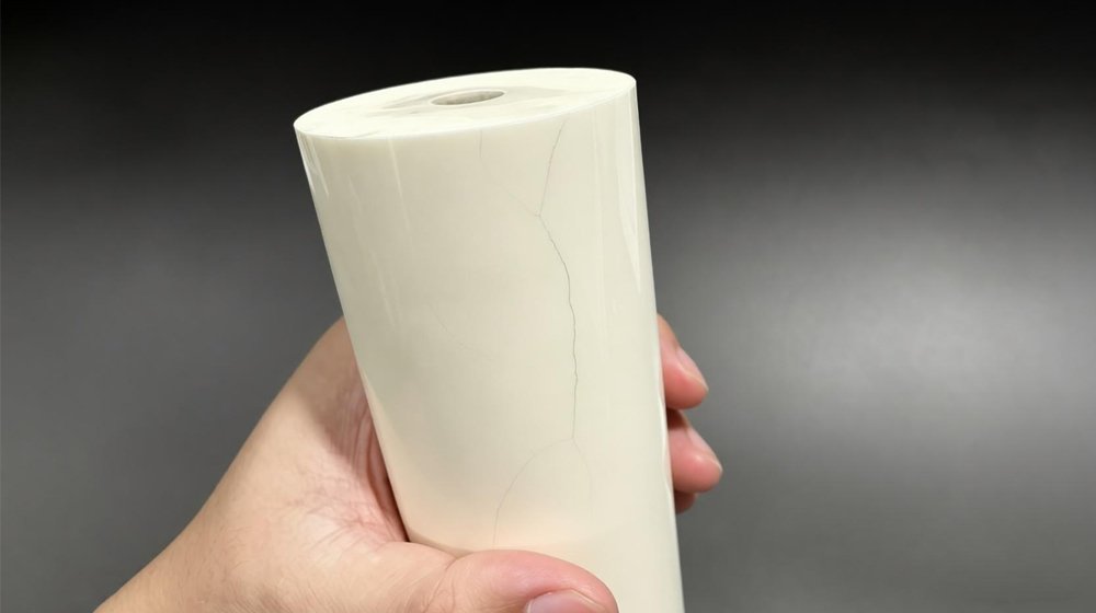
2. Microcracks caused by machining are the most insidious and fatal form of failure. These cracks are difficult to detect with the naked eye and slowly propagate during use, eventually leading to fracture.
3. We need to anticipate failure risks in advance. Selecting a reliable supplier is crucial to ensuring production line stability.
Next, we will skip the theory and go straight to a practical perspective, clearly explaining the causes of ceramic failure and methods for early risk management.
Ceramic Failure Modes
Thermal Shock Failure
Ceramic materials are highly sensitive to rapid heating and cooling. When equipment starts up or stops, is cleaned, or processes change, causing sudden temperature changes, the surface and interior of the material expand and contract at different rates. If the resulting thermal stress exceeds its tolerance limit, it can lead to penetrating cracks.
Furthermore, mismatched thermal shock resistance and uneven wall thickness can also cause thermal stress imbalance. Excessively tight assembly restricting thermal expansion can also lead to failure.
Engineering Advice:
1. In applications involving frequent thermal cycling, prioritize the use of silicon nitride or silicon carbide materials.
2. Avoid abrupt changes in wall thickness in the design.
3. After rough grinding, add fine grinding and polishing processes to eliminate surface tensile stress.
Stress Concentration Failure
Parts fracture before reaching their design load, often at sharp corners, hole edges, or steps. Common causes include sharp internal corners, abrupt changes in wall thickness, and improper machining of deep holes or thin walls.
Engineering Advice:
1. Internal corner radii should be at least ≥0.5mm, and external corner radii at least ≥0.2mm.
2. Avoid sharp corners.
3. The depth-to-diameter ratio of stress-bearing holes should be ≤5.
4. Critical areas require dye penetrant testing.
Microcrack Failure Caused by Machining
Microcracks, invisible to the naked eye, are easily generated during machining processes such as milling and grinding. Although the appearance of such parts meets specifications, they may suddenly fracture after several weeks of operation.
Improper grinding parameters (e.g., depth of cut > 20μm, excessively high wheel speed) and insufficient coolant supply are all contributing factors to crack failure.
Engineering Advice:
1. Establish standardized grinding parameters (e.g., control the depth of cut for alumina ceramics to 5-10μm).
2. Conduct destructive strength sampling tests before mass production.
3. Critical components should undergo dye penetrant testing.
Dimensional/Surface Quality Failure
Dimensional deviations, failure to meet flatness/parallelism requirements, or warping and deformation prevent the part from meeting precision assembly requirements.
Alternatively, excessive surface roughness, scratches, or chipped edges can compromise sealing performance and wear resistance, ultimately leading to failure.
Material Selection Failure
The operating conditions meet design requirements, but abnormal wear or premature fracture still occur. This may be due to inappropriate material selection, such as using alumina for high-impact conditions, zirconia for high-temperature environments, or incompatible materials for strong acid media.
Quick Selection Checklist:
| Key Operating Requirements | Preferred Material | Prohibited Material |
| Normal wear, cost-sensitive | Alumina | — |
| Subject to impact, vibration, or food contact | Zirconia | Alumina |
| High temperatures (>1000℃); requires heat transfer | Silicon carbide | Zirconia |
| High-speed rotation; frequent thermal cycling | Silicon nitride | Alumina |
Quick Tips for Identifying Failure Modes
1. A smooth and uniform fracture surface → often caused by stress concentration or overload.
2. Dark areas or delamination on the fracture surface → often caused by microcracks caused by machining or internal defects.
3. Repeated fractures at the same location → may indicate design or material selection issues.
Ceramic Failure Prevention
To effectively reduce the probability of ceramic failure, it is necessary to implement phased control measures from material preparation to the operating environment.
Material Preparation
- If the blank contains pores, cracks, or impurities, it should be discarded immediately.
- If the stress is too high after sintering, a low-temperature annealing process can be used to eliminate residual thermal stress.
- Round off the edges to prevent sharp corners from becoming stress concentration points.
Special Note: It is essential to pay close attention to potential internal defects in the blank. If these defects are not removed in time before entering the machining stage, delayed cracking may easily occur later.
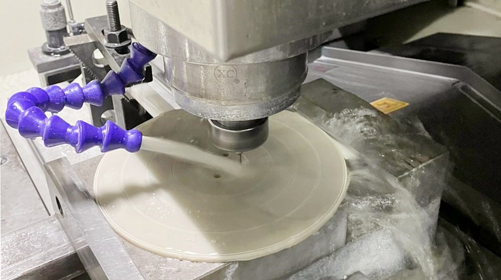
Machining Process
- Use vacuum clamping or flexible fixtures to ensure uniform clamping force and prevent excessive local pressure.
- Use diamond or CBN superhard tools during machining. Replace tools immediately when dull. Avoid vertical cutting. Use helical or ramp entry methods and implement a machining strategy of “high speed, low feed, and shallow depth of cut.”
- Use mist cooling to prevent thermal shock. Remove chips promptly to prevent secondary scratches on the surface.
Special Note: Do not directly apply metalworking experience to ceramic machining. Improper parameter settings can lead to the accumulation of thermal stress and vibration, ultimately causing machining failure.
Process Monitoring
- If the spindle load display is abnormal, stop the machine immediately and check the tool wear and cutting depth.
- After machining 5-10 pcs, randomly check the dimensions. If the dimensional fluctuation suddenly increases, it is a warning signal of abnormal parameters. Do not wait until the entire batch is finished before checking.
- Reduced coolant flow or nozzle blockage will affect heat dissipation. If there is obvious smoke or odor, it indicates that the cooling has failed.
Special Note: It is recommended to leave a machining allowance of 0.05-0.1mm during rough grinding for fine grinding. Even if minor problems occur during rough grinding, they can still be remedied during fine grinding.
Post-processing and Usage Stage
- Residual stresses from machining can be relieved through low-temperature annealing.
- Hidden cracks can be detected using dye penetrant testing, which causes the affected areas to become visible. This method is simple and effective.
- Avoid sudden temperature changes during use. If necessary, use gradual heating or cooling. For load-bearing structural components, computer simulations should be used to predict stress concentration zones.
Special Note: After sintering, inspect density, dimensions, and appearance. After machining, inspect dimensional tolerances, geometrical accuracy, and surface quality. Critical components require 100% non-destructive testing to prevent hidden defects from reaching the customer.
Ceramic Quality Risk Control
Customers can evaluate whether a supplier has the necessary ceramic machining capabilities by considering the following factors:
| Evaluation Criteria | Capabilities required of a qualified supplier |
| Design Support | Provide DFM reports and proactively assist with design optimization. |
| Manufacturing Capabilities | Maintain standard processes and can provide grinding parameters for various materials. |
| Inspection Capabilities | Possess capabilities for dye penetrant testing and standard dimensional inspection. |
| Quality Traceability | Assign a batch number to each batch for traceability; provide process data. |
| Failure Analysis | Can issue failure analysis reports and determine the root cause of failures. |
Conclusion
Risk control in ceramic machining is not essentially about achieving an ideal state of “never breaking,” but rather about systematic failure analysis. This involves identifying risk sources during the design phase, controlling key variables during machining, effectively detecting defects during inspection, and continuously providing feedback and optimization during actual use.
In our past typical engineering cases, by implementing the above closed-loop management approach, the failure rate of ceramic components has typically been reduced by approximately 50%–80%, and the Mean Time Between Failures (MTBF) has increased by several times.
It is important to emphasize that relying solely on material substitution often fails to address the root cause of the problem. In contrast, establishing a verifiable and traceable control system throughout the entire process from design and manufacturing to application is the key path to achieving long-term stable operation.
Frequently Asked Questions
Q1: Can ceramic machining parameters be directly copied from data found online?
A1: No. Due to variations in green body batches, grinding wheel brands, and machine tool rigidity, the machining results can vary significantly even when using the same parameters.
We recommend starting with a small-batch trial run, recording the parameters as you go. Once you have identified the optimal parameters for your specific equipment setup, you can then finalize them.
Q2: The ceramic components are now in use. How can we maintain them on a daily basis to extend their service life?
A2: We have the following suggestions:
1. Regularly inspect the surface for scratches or chipped edges.
2. Avoid frequent starts and stops of the equipment; maintain continuous operation whenever possible.
3. When cleaning, wait for the ceramic components to cool down before rinsing with water. Never rinse hot components directly.
4. Record the installation time and failure time for each batch of ceramic components.
5. If fractures repeatedly occur in the same location, do not simply replace the parts; also investigate whether there are issues with the design or component selection.
Q3: How should I handle the risk of ceramic components cracking under pressure during assembly?
A3: Ceramic components are susceptible to localized stress, impact, and excessive tightening in specific areas. Following these key points will ensure safe assembly:
1. Fitting surfaces must be chamfered to avoid sharp corners.
2. Clamping force must be applied evenly; never apply excessive force to a single point.
3. Do not strike the ceramic components.
4. If conditions permit, place a layer of copper sheet between the parts.
5. Torque must be applied strictly according to specified values; do not rely solely on feel.
Q4: Is dye penetrant testing required for all products?
A4: Not necessarily. For general-purpose ceramic parts, dimensional inspection combined with visual inspection is generally sufficient.
However, for applications requiring high reliability, or where the product is subject to alternating loads or temperature cycling, dye penetrant testing is recommended to prevent situations where a part appears visually acceptable but fractures during use.