
Introduction
Precision ceramic components are widely used in industries that require extreme reliability, high temperature resistance and excellent wear performance. Compared with traditional metals or polymers, advanced ceramics provide unique mechanical, thermal and electrical properties that enable engineers to solve challenging design problems.
In semiconductor equipment, medical devices, aerospace systems and vacuum electronics, precision ceramic parts often play critical roles such as insulation, sealing, thermal management and structural support.
However, designing and machining ceramic parts is very different from designing metal components. Ceramics are hard but brittle, and they require special machining processes and careful structural design.

Understanding the design rules and machining processes of ceramic components is essential for engineers who want to develop reliable and cost-effective products.
This guide explains the key considerations in precision ceramic design and machining, including materials, machining methods, design rules and common engineering mistakes.
What Are Precision Ceramic Parts
Precision ceramic parts refer to engineering components manufactured from advanced ceramic materials using high-precision machining processes. Unlike traditional ceramics used in pottery or construction materials, engineering ceramics are designed to achieve specific mechanical and thermal properties.
These materials typically exhibit:
-
Extremely high hardness
-
Excellent wear resistance
-
High temperature stability
-
Chemical corrosion resistance
-
Electrical insulation properties
Because of these properties, precision ceramic components are often used in harsh environments where metals or plastics cannot perform reliably.
Typical precision ceramic components include:
-
Semiconductor equipment parts
-
Insulators and feedthrough components
-
Ceramic bearings
-
Vacuum sealing components
-
High temperature structural parts
Why Engineers Use Advanced Ceramic Components
Engineers often choose ceramic materials when conventional materials fail to meet performance requirements.
One of the most important advantages of advanced ceramics is their exceptional hardness. For example, alumina ceramics can reach hardness values close to sapphire, while silicon carbide is even harder than many hardened steels. This makes ceramic parts highly resistant to wear and abrasion.
Another important advantage is high temperature stability. Many ceramic materials can operate at temperatures exceeding 1000°C without significant deformation.
In addition, ceramics offer excellent electrical insulation and corrosion resistance, making them ideal for electronic and chemical environments.
For example, in one of our previous business collaborations, a semiconductor equipment manufacturer required a component capable of operating in a high-temperature plasma environment. At the time, the client’s critical components were made of metal; however, after a period of use, they experienced corrosion and generated particulate contamination.
Considering that this workpiece needs to meet certain conditions:
-
High thermal stability
-
Low particle generation
-
High wear resistance
we recommend changing the material of the part to silicon carbide. After switching to ceramic materials, the component lifetime increased significantly and contamination was reduced.
Common Materials Used in Precision Ceramic Parts
Several advanced ceramic materials are commonly used in precision engineering applications.
Alumina (Al₂O₃)
Alumina ceramics are the most widely used engineering ceramics. They offer a good balance of hardness, electrical insulation and cost.
Applications include electronic substrates, insulators and wear components.
Zirconia (ZrO₂)
Zirconia ceramics are known for their exceptional fracture toughness. Compared with other ceramics, zirconia is less brittle and more resistant to impact. This material is often used in mechanical components and medical devices.
Silicon Carbide (SiC)
Silicon carbide ceramics offer extremely high hardness and excellent thermal conductivity. They are widely used in semiconductor manufacturing equipment.
Silicon Nitride (Si₃N₄)
Silicon nitride ceramics combine high strength with good thermal shock resistance. They are commonly used in high-speed bearings and engine components.
Engineers often need to choose between ceramics, metals and polymers when designing components. Each material category offers different advantages and limitations.
Material Comparison: Ceramic vs Metal vs Polymer
| Property | Ceramics | Metals | Polymers |
|---|---|---|---|
| Hardness | Very High | Medium | Low |
| Wear Resistance | Excellent | Moderate | Poor |
| Temperature Resistance | Very High | High | Low |
| Electrical Insulation | Excellent | Poor | Good |
| Fracture Toughness | Low–Medium | High | Medium |
| Density | Medium | High | Low |
Key Design Rules for Ceramic Components
Designing ceramic components requires a very different engineering mindset compared with metal part design. Ceramics are extremely hard and strong in compression, but they are also brittle and sensitive to tensile stress. Because of these characteristics, improper design can easily cause cracking or failure during machining or operation.
Engineers must follow several important design rules when working with ceramic materials. These rules help reduce stress concentration, improve manufacturability, and ensure long-term reliability.
Wall Thickness Design Guidelines
Uniform wall thickness is one of the most important factors in ceramic component design. Large thickness variations may cause internal stresses during sintering or machining.
These stresses may lead to distortion or cracking.
Recommended Wall Thickness
| Component Size | Recommended Thickness |
|---|---|
| Small components | ≥0.5 mm |
| Medium components | ≥1 mm |
| Large structural parts | ≥2–3 mm |
Maintaining a uniform wall thickness can significantly reduce machining difficulty and improve structural reliability.
Fillets and Edge Design
Sharp edges should always be avoided when designing ceramic parts. Sharp corners create stress concentration points where cracks can easily initiate. Instead, engineers should use fillets or rounded transitions.
Recommended Fillet Radius
| Feature | Recommended Radius |
|---|---|
| Internal corners | ≥0.5 mm |
| External edges | ≥0.3 mm |
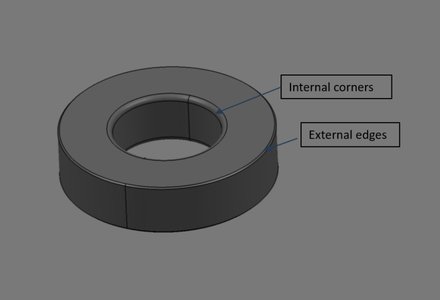
Rounded edges also improve machining efficiency and reduce the risk of edge chipping.
Hole Design Considerations
Hole structures are common in ceramic components but require careful design. Deep or narrow holes are difficult to machine and may cause tool wear or breakage.
Recommended Hole Design
| Parameter | Recommendation |
|---|---|
| Minimum hole diameter | ≥0.5 mm |
| Maximum depth ratio | ≤5× diameter |
| Minimum spacing between holes | ≥2× diameter |
Following these guidelines improves machining stability and reduces production cost.
Cost Optimization
Many engineers assume ceramic components are always expensive. In reality, cost depends heavily on design decisions. By optimizing design parameters, engineers can significantly reduce machining cost.
Major factors affecting cost include:
| Factor | Impact on Cost |
|---|---|
| Material type | SiC and Si₃N₄ are more expensive |
| Part size | Large parts require longer machining time |
| Tolerance | Tight tolerances increase grinding time |
| Surface finish | Polishing processes increase cost |
| Hole complexity | Deep holes increase machining difficulty |
Design Tips to Reduce Cost
- Avoid extremely tight tolerances unless necessary.
- Use standard geometries whenever possible.
- Minimize deep holes and thin walls.
- Maintain uniform wall thickness.
These strategies can reduce machining time and improve yield.
Common Machining Methods for Precision Ceramic Parts
Machining advanced ceramics requires specialized equipment and tools. Because ceramics are extremely hard, conventional cutting tools cannot be used. Most ceramic machining processes rely on diamond tools.
The two main stages of ceramic machining are:
-
Green machining (before sintering)
-
Hard machining (after sintering)
Grinding Processes for Ceramic Components
Grinding is the most common machining process for precision ceramic parts. Diamond grinding wheels are used to remove material gradually.
Typical grinding operations include:
-
Surface grinding
-
Cylindrical grinding
-
Internal grinding
Typical Grinding Capabilities
| Process | Accuracy |
|---|---|
| Surface grinding | ±5 μm |
| Cylindrical grinding | ±3 μm |
| Internal grinding | ±5–10 μm |
Lapping and Polishing
Lapping and polishing are finishing processes used to achieve extremely smooth surfaces. These processes are widely used in sealing surfaces and optical components.
Typical surface roughness values include:
| Process | Surface Roughness |
|---|---|
| Fine grinding | Ra 0.2–0.4 μm |
| Lapping | Ra 0.05–0.2 μm |
| Polishing | Ra <0.01 μm |
Common Problems in Ceramic Machining
Although ceramics provide excellent performance, machining them can be challenging. Several common defects may occur during machining.
Micro Cracks
Micro cracks are small fractures that appear on or below the surface of the ceramic. They are usually caused by excessive grinding force or thermal stress. If not removed during finishing processes, micro cracks may propagate during service.
Edge Chipping
Edge chipping occurs when small fragments break off from the edges of the component. This defect is common in thin sections or sharp edges. Proper chamfer design can significantly reduce this problem.
Subsurface Damage
Subsurface damage refers to micro defects beneath the surface layer. These defects may reduce strength and reliability. Precision polishing is often required to remove damaged layers.
Precision Ceramic Machining Parameters
Machining parameters play a crucial role in preventing defects such as micro cracks and edge chipping. Proper grinding parameters improve surface quality and tool life.
| Parameter | Typical Range |
|---|---|
| Grinding wheel speed | 20–35 m/s |
| Feed rate | 0.005–0.02 mm/rev |
| Depth of cut | 2–20 μm |
| Coolant | Water-based coolant |
Using sufficient coolant is essential to prevent thermal stress and surface cracking.
Surface Finishing and Quality Inspection
Quality inspection is critical for precision ceramic components. Several inspection techniques are commonly used.
Dimensional Inspection
-
Coordinate Measuring Machine (CMM)
-
Optical measurement systems
Surface Inspection
-
Surface roughness tester
-
Optical microscope
Structural Inspection
-
X-ray inspection
-
Ultrasonic testing
Applications of Precision Ceramic Components
Precision ceramic parts are widely used across many industries.
Semiconductor Industry
-
Wafer handling components
-
Plasma chamber parts
Medical Devices
-
Surgical instruments
-
Implant components
Aerospace and Energy
-
High temperature insulation parts
-
Wear resistant mechanical components
Design Mistakes Engineers Should Avoid
Several design mistakes frequently appear in ceramic component projects.
-
Wall thickness too thin
-
Sharp corners without fillets
-
Extremely deep holes
-
Unrealistic tolerance requirements
-
Ignoring machining limitations
Avoiding these mistakes can significantly reduce manufacturing cost and improve reliability.
How to Choose a Reliable Ceramic Manufacturer
Selecting an experienced ceramic manufacturer is critical for successful projects. Important factors include:
-
Manufacturing capability
-
Machining equipment
-
Quality control system
-
Engineering support
Working with a manufacturer who understands ceramic design can prevent costly design mistakes.
Conclusion
Precision ceramic components play an increasingly important role in modern engineering applications. However, successful ceramic component design requires a deep understanding of material properties, machining methods and structural design rules. By following proper design guidelines and working with experienced manufacturers, engineers can fully leverage the advantages of advanced ceramic materials.