

Introduction
In the rapidly evolving semiconductor and microelectronics industries, advanced ceramics have become the cornerstone of high-power thermal management. Materials such as Alumina (Al₂O₃), Aluminum Nitride (AlN), and Silicon Nitride (Si₃N₄) are widely selected for their exceptional thermal conductivity and electrical insulation. However, processing these brittle, ultra-hard materials using traditional mechanical dicing presents significant challenges. This is where laser cutting of ceramic substrates emerges as the gold standard for high-precision manufacturing.
Many of us were familiar with and used stamps two or three decades ago. A large sheet of stamps was printed on a large sheet of paper, with numerous densely packed perforations neatly arranged to divide the space. To use a smaller stamp, one simply tore it along the perforations. Ceramic substrates are processed in a similar way.
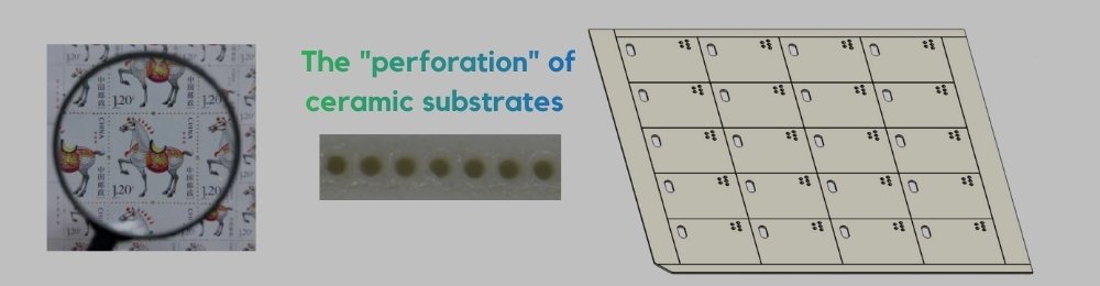
Of course, ceramics are not as easily processed as paper. Ceramics are both hard and brittle. Using traditional mechanical methods to create these numerous tiny pores can easily lead to chipping and microcracks at the edges of the ceramic substrate. These defects are fatal hazards in high-voltage, high-power semiconductor applications. This article will introduce this alternative to ceramic substrates, showing you the “invisible scalpel” that modern manufacturing uses for ceramic substrates—laser cutting technology.
Laser Cutting Principle of Ceramic Substrates
Laser cutting, also known as scribing or controlled fracture cutting, works as shown in the diagram below. A laser beam, guided by the processing equipment’s light guide system, is focused onto the surface of the ceramic substrate. Due to the laser’s focusing effect, the beam is concentrated into an extremely small point (typically tens of micrometers, thinner than a human hair). Light energy is converted into heat energy, instantly generating extremely high energy. A tiny area of material on the ceramic substrate is melted and further vaporized, leaving a row of tiny pits or shallow grooves. Because the heat is highly concentrated, the impact on surrounding materials is minimal.
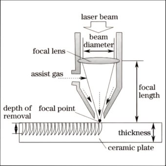
Laser Cutting Principle of Ceramic Substrates
Interconnected blind holes (grooves) form on the ceramic surface, much like the closely spaced perforations on a large stamp sheet. If stress is applied along the scribing area, the material easily and accurately breaks along the scribing line due to stress concentration, completing the slicing process.
Several Key Factors in Laser Cutting
Speed:
Each blind hole left by laser irradiation on a ceramic substrate is generated by a single pulse, meaning one hole corresponds to one pulse. Therefore, theoretically, the density of blind holes determines the processing time of laser cutting. We can assume that the diameter of the hole created by each pulse is D1, and the diameter of the entire heat-affected zone surrounding the hole is D2 (D2>D1). The overlap rate of ceramic dicing is generally calculated based on D2, ranging from 0% to 50%. This ensures that the heat diffusion areas caused by each pulse’s energy are interconnected, facilitating dicing.
When calculating and estimating the laser cutting speed, we assume the laser frequency during dicing is f. We can then derive the maximum dicing speed Vmax and minimum dicing speed Vmin as:
Vmax = f*D2, Vmin = f*D2/2.
Effective laser cutting on ceramic substrates falls between these two speeds.
Depth:
Generally, a scribing depth of 1/4 to 1/3 of the ceramic thickness is sufficient for satisfactory dicing. Currently, most customers use 45% to 55% of the thickness as the scribing depth, which is a more convenient and suitable value for dicing ceramic sheets.
Materials:
Commonly used materials for ceramic substrate wafer fabrication are currently 96% alumina , aluminum nitride and silicon nitride. Tailoring parameters for your ceramic applications are as follow:
| Ceramic Material | Recommended Laser Type | Key Application Fields |
|---|---|---|
| 96% / 99% Alumina (Al₂O₃) | CO2 / Fiber Laser | Standard PCB Substrates, Resistor Networks |
| Aluminum Nitride (AlN) | UV / Fiber Laser | High-Power LEDs, Semiconductor Laser Diodes |
| Silicon Nitride (Si₃N₄) | Ultrafast (Picosecond) | Automotive EV IGBT Modules, Aerospace Electronics |
Positioning Holes:
Most customers order 114x114mm original substrates. This size facilitates mass production of circuit boards on the machine. A positioning hole (0.5mm in diameter) is added to the non-functional area of the large substrate for easy positioning and identification by the machine. After the circuitry on the original large substrate is mass-produced, it is then sliced according to the pre-cut laser dimensions (a*b mm) for subsequent processes.
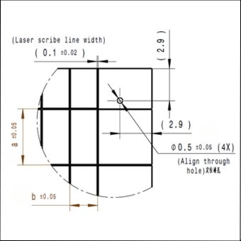
Diagram of positioning holes on Ceramic Substrates
Laser Cutting core advantages
Laser cutting, because it involves a laser directly ablating and vaporizing the material along a pre-defined size and contour line, offers several significant advantages as a “non-contact” processing method:
1. No mechanical stress, extremely high quality:
Without the wear of cutting tools or physical pressure between the laser and the product, it fundamentally avoids quality issues such as edge chipping and micro-cracks. These quality problems are common in the machining of ceramic products and affect their functionality. The “non-contact” method ensures the edge strength of the ceramic substrate (especially ultra-thin substrates), which is crucial for long-term reliability in harsh environments.
2. King of precision and flexibility:
The extremely small laser spot allows for the cutting of extremely complex and precise contours. Whether it’s irregular holes, fine-pitch adjustments, or changes to the design contour, only modifications to the drawings on the computer are needed; no physical molds need to be replaced. This makes it particularly suitable for small-batch, multi-variety R&D and high-value-added production.
3. Efficiency and automation:
Laser cutting is fast and easily integrated into automated production lines, enabling continuous operation from sheet material to finished product, thus increasing overall production capacity.
In short, when you are looking for high reliability, high precision and fast prototyping, laser processing is almost the only option for ceramic substrate segmentation.
Overcoming Common Defects in Ceramic Laser Scribing
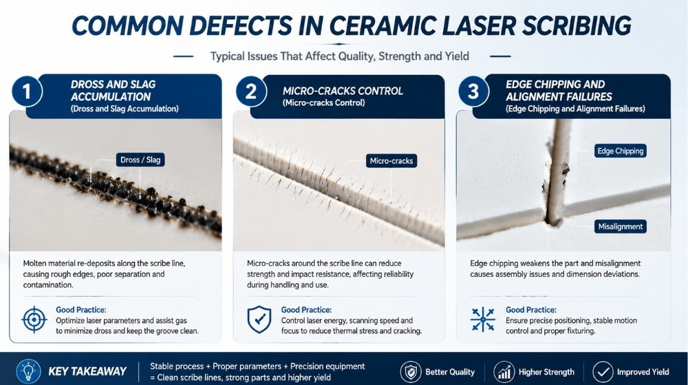
Industrial manufacturers often encounter quality bottlenecks during high-speed laser dicing. Understanding these defects is the first step toward process optimization:
When molten ceramic re-solidifies along the kerf edges, it forms stubborn debris. By integrating high-pressure, coaxial inert assist gases, the molten alumina is cleanly blown away before re-solidification, ensuring smooth, burr-free edges.
To prevent misalignment during consecutive breaking processes, incorporating high-precision positioning features is mandatory. Designing automated laser-drilled alignment holes (typically ∅ 0.5mm) allows optical CCD cameras to calibrate the dicing grid accurately, dropping post-snap rejection rates close to 0%.
At Jinghui Ceramics, we combine years of precision manufacturing expertise with state-of-the-art laser technology to deliver flawless ceramic sub-mounts. Contact our engineering team today at sales@jinghui0738.com to optimize your next microelectronics project.