
Introduction
In applications such as electric vehicles (EVs), industrial drives, and photovoltaic inverters, the power density of power modules continues to increase, leading to a significant increase in internal heat generation. Based on experience from actual projects, we believe that the core cause of power module failures is usually not circuit design flaws, but rather insufficient cooling system efficiency or the inability of materials to withstand long-term thermal stress.
Therefore, the importance of the ceramic substrate is increasingly prominent, as it is a key component ensuring the stable operation of the power module. Its core functions offer rapid heat dissipation, electrical insulation, and maintain performance stability under high temperatures and repeated thermal shocks. Practical experience has proven that the long-term stable operation of a power module depends not only on chip performance but also on the rationality of the substrate selection and structural design.
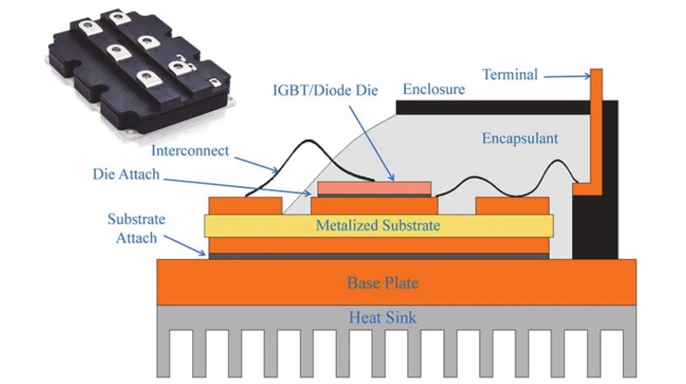 Fig. 1-Structure of IGBT
Key points:
- Ceramic substrates serve two core functions: heat dissipation channels and electrical insulation layers. Both aspects must be considered simultaneously.
- Commonly used ceramic substrate materials have their strengths: alumina (Al2O3) substrates lies in their high cost-effectiveness, aluminum nitride (AlN) prioritizes heat dissipation performance, while Silicon nitride (Si3N4)’s core highlight is its outstanding reliability.
- From a manufacturing perspective, DBC substrate technology is very mature and has a significant cost advantage; AMB technology offers higher bonding strength and is often preferred, especially in scenarios with stringent reliability requirements.
- The module’s heat dissipation performance is not solely determined by the substrate material; the thickness of the copper layer and the overall structural design also play crucial roles.
- From actual failure cases, most malfunctions stem from long-term accumulation of thermal stress or inherent defects in the material itself.
- Substrate selection ultimately involves system-level trade-offs, finding a proper balance between performance, lifespan, and cost.
What Is a Ceramic Substrate for Power Modules?
Simply put, the ceramic substrate is the layer sandwiched between the chip and the heat dissipation system. Although it is just an intermediate layer, its role is very important:
1. Work as a carrier to provide mechanical support for the entire product;
2. Provide electrical isolation to ensure product safety;
3. Conduct the heat generated by the chip downwards.
The common structure of power modules is as follows: Chip → Solder → Copper layer → Ceramic → Base plate → Heatsink
In ordinary electronic devices, this layer may not be very noticeable due to their low operating power. However, it plays a crucial role in high-power applications. It is not just a “transition layer”, but a core component that directly affects heat dissipation efficiency and long-term reliability.
Why Are Ceramic Substrates Irreplaceable?
In high-power applications, using traditional PCB materials easily leads to these problems:
- Insufficient thermal conductivity, preventing heat dissipation from the chip;
- Deteriorating insulation performance at higher voltages;
- Mismatched thermal expansion coefficients of various materials make components prone to cracking after repeated thermal cycling.
These problems, combined, are difficult to solve through structural optimisation completely. The advantage of ceramic materials lies in their ability to address these issues simultaneously: they provide both thermal conductivity and insulation, while maintaining greater stability in size and performance under temperature variations.
Therefore, ceramic substrates are almost universally used in applications with high performance and reliability requirements, such as electric drive systems for electric vehicles, photovoltaic inverters, and industrial motor drives. In these applications, ceramic substrates are a standard configuration and difficult to replace with other materials.
Comparison of Common Ceramic Materials
Key takeaway :
1. Alumina substrate: Low price, mature technology, and the widest range of applications; mainly used in conventional applications with low power and cost sensitivity.
2. Aluminium nitride substrate: Excellent thermal conductivity and outstanding heat dissipation capacity; mostly used in mid-to-high-end power modules with high heat dissipation requirements.
3. Silicon nitride substrate: High mechanical strength, impact resistance, resistance to thermal cycling, and extremely high reliability; mainly used in harsh applications such as automotive, high reliability, and long-term stable operation.
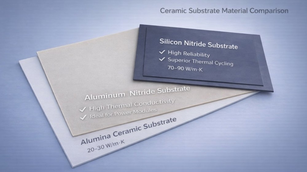 Fig. 2-Comparison of Common Ceramic Materials
Many customers ask which of the three ceramic materials, Al₂O₃, AlN, and Si₃N₄, is better for making substrates. In fact, there is no “best material,” only “more suitable choice.” These three materials differ significantly in thermal conductivity, mechanical strength, and cost; their applicable scenarios also differ. Below is a comparison table of the performance and application scenarios of the three materials:
| Property | Alumina (Al₂O₃) substrate | Aluminum nitride (AlN) substrate | Silicon nitride (Si₃N₄) substrate |
| Thermal conductivity | Low (20~30 W/m・K) | High (170~230 W/m・K) | Medium (70~90 W/m・K) |
| Mechanical strength /
Crack resistance |
Average strength with relatively brittle | Relatively brittle with low impact resistance | Extremely high toughness and not easily cracked |
| Electrical insulation | Good | Excellent | Excellent |
| Coefficient of thermal expansion (CTE) | Moderate | High compatibility with silicon chips | Moderate |
| Cost | Low cost, but high performance/cost | High | Higher |
| Main highlights | Mature, inexpensive, and versatile | Excellent thermal conductivity and good insulation | Extremely high strength, impact-resistant, and thermal shock-resistant |
| Typical applications | Home appliance power supplies, general industrial power supplies, low-power modules | Photovoltaic inverters, communication power supplies, medium and high power modules | Electric vehicle on-board, motor drive, high-reliability, high-power module |
Direct Copper Clad(DBC) vs Active Metal Brazing(AMB)
Regular substrate metallization processes are DBC and AMB. The choice of which one to use usually depends on the project’s priorities.
DBC (Direct Copper Clad)
● The process is mature and has the widest range of applications;
● Costs are relatively more controllable;
● It can basically meet the needs of most conventional industrial applications.
AMB (Activated Metal Brazing)
● Stronger bonding force between copper and ceramic;
● Better resistance to thermal cycling;
● More suitable for applications with high reliability requirements.
Engineering insight
● If cost and versatility are prioritised in a project, DBC is typically chosen.
● For high-power, long-life, or demanding applications, AMB is preferred.
Essentially, it’s still a trade-off between cost/performance and high reliability. For more information, please see: Comparison of DBC and AMB process technologies.
Thermal Performance and Heat Dissipation Path
From a heat transfer perspective, the general path is as follows: Chip → Copper Layer → Ceramic → Base Plate → Heatsink. In other words, heat is transferred downward, and any poorly designed layer can become a bottleneck.
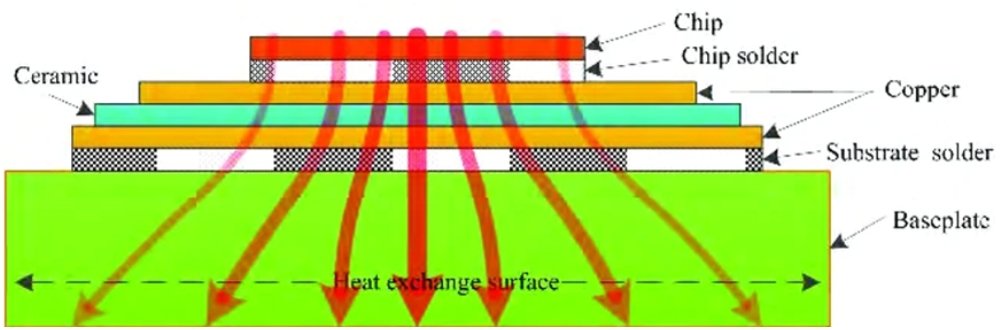
Fig.3-The Schematic Diagram of Heat Dissipation Path
The overall heat dissipation performance of a power module is mainly determined by the thermal conductivity of the materials themselves, the thickness of the copper layer, and the thickness of the ceramic substrate. When designing, engineers shouldn’t focus solely on a single parameter, such as simply increasing thermal conductivity or excessively thickening the copper layer; the effect is often limited. A more reasonable approach is to consider the entire heat path together, coordinating materials, structure, and dimensions to truly optimize the overall heat dissipation of the product.
To learn more, please see: How do ceramic substrates improve heat dissipation in power electronics?
Failure Mode and Reliability
In practical use, most ceramic substrate failures do not occur suddenly, but rather accumulate gradually over time. Typical failure modes include: copper layer peeling, ceramic cracking, and insulation breakdown. Looking deeper, the causes generally fall into the following categories:
● Defects in the material itself, as shown in the following figure 4;
● Fatigue caused by long-term thermal cycling of the product;
● Inadequate structural design leading to stress concentration.
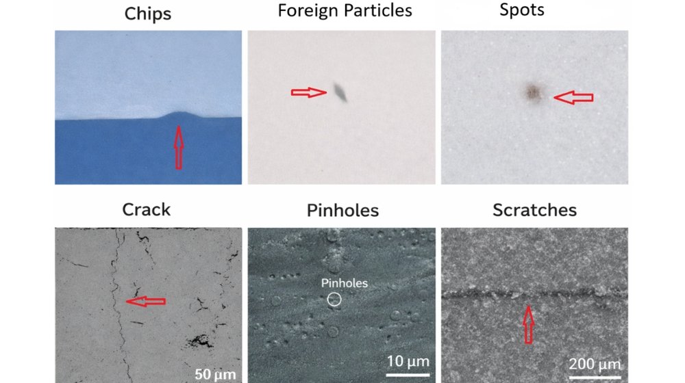 Fig.4-Ceramic Substrate Defects Overview
Case Study: DBC Substrate Insulation Breakdown
● Quality issue:
A high-voltage industrial module, rated at 3300V, initially operated normally. After a period of operation, the internal insulation layer of the module experienced a breakdown failure.
● Cause Analysis:
Subsequent inspection revealed micropores within the ceramic substrate. Under high electric field conditions, these tiny defects create localized electric field concentrations, which, over time, trigger breakdown.
● Engineering Conclusion:
The breakdown voltage of a 0.5 mm thick alumina substrate is typically in the range of 12–18 kV. While appropriately increasing the thickness of the ceramic substrate can effectively improve the breakdown strength, the improvement is not linear. Internal material defects and edge electric field effects are often the decisive factors.
In actual projects, improving product reliability cannot simply be achieved by “thickening” the ceramic substrate; it is crucial to consider both material quality and structural design.
For more details, please see: Common Failure Modes of Ceramic Substrates for Power Modules
Common Design Pitfalls
We’ve worked on many projects, and when product issues arise, the common assumption is that the materials are faulty. However, an in-depth review often reveals that the problems were rooted in the design phase.
Common issues include:
- Failure to consider material thermal expansion matching, potentially leading to cracking of the substrate or the interface between the substrate and copper layer after repeated thermal cycling;
- Excessively thick copper layers, while improving thermal conductivity, also increase stress, causing various failures;
- Incorrect substrate thickness selection—either too thin, resulting in insufficient strength or too thick, degrading heat dissipation;
- Material selection solely based on cost, ignoring actual operating conditions;
- Failure to consider long-term thermal cycling in the design results in normal operation initially, but problems later.
In our engineering practice, we’ve found that the lifespan of many modules is largely determined in the design phase, leaving little room for adjustment later.
How to Choose a Right Ceramic Substrate?
In the engineering field, substrate selection is essentially a trade-off between performance, reliability, and cost; there’s no single, universally applicable standard answer. As a ceramics manufacturer, we typically offer advice based on the following key dimensions:
1. From a power density perspective
For low to medium power applications, Al₂O₃ is sufficient and offers good cost-effectiveness; however, as power density increases, the heat dissipation pressure rises, at which point AlN materials must be considered. In actual projects, we recommend choosing AlN whenever the power density exceeds 100 W/cm², and in most cases, this is the only feasible option.
For power density above 100 W/cm², AlN is typically the only practical option.
2. From reliability requirements
For ordinary industrial applications, DBC plus Al₂O₃ or AlN is sufficient; however, for scenarios with high requirements for lifespan and stability, such as new energy equipment and equipment used in harsh environments, a combination of Si₃N₄ + AMB is recommended.
3. From the perspective of thermal cycling conditions
If the equipment is frequently started and stopped and the temperature fluctuates repeatedly, Si₃N₄ has a greater advantage in terms of resistance to thermal fatigue; conversely, if the operating conditions are relatively stable, Al₂O₃ or AlN can meet the requirements.
4. From voltage levels
A fundamental principle in power module design is that higher voltage demands higher insulation from the substrate. There are typically two solutions: one is to make the substrate thicker, and the other is to use a material with better insulation properties. Using both methods in combination provides greater stability.
5. From a cost perspective
If the project is particularly cost-sensitive and prioritises ultimate cost-effectiveness, then the Al₂O₃ + DBC combination is the first choice;
If performance and long-term reliability are more important, then the AlN or Si₃N₄ + AMB solution is more recommended.
Engineering Experience Summary:
In our real projects, we’ve found that substrate selection is never based on a single metric. We typically consider factors such as thermal load, mechanical stress from the structure, product lifespan, and cost. The final solution is derived from a comprehensive weighing of all these factors; we don’t simply choose the best material, but rather the most suitable option.
To learn more, please see: How to choose the right ceramic substrate?
Typical Applications
Currently, ceramic substrates are primarily used in applications with high power and reliability requirements, as shown in Figure 4, such as
- Power modules in electric vehicles (like IGBTs and SiC)
- Photovoltaic inverters
- Industrial motor drive systems
- Various high-power electronic devices
These applications share a common characteristic: they have very high requirements for heat dissipation, insulation, and long-term stability, which traditional materials (FR-4) simply cannot meet. Therefore, ceramic substrates are now basically the standard for these applications.
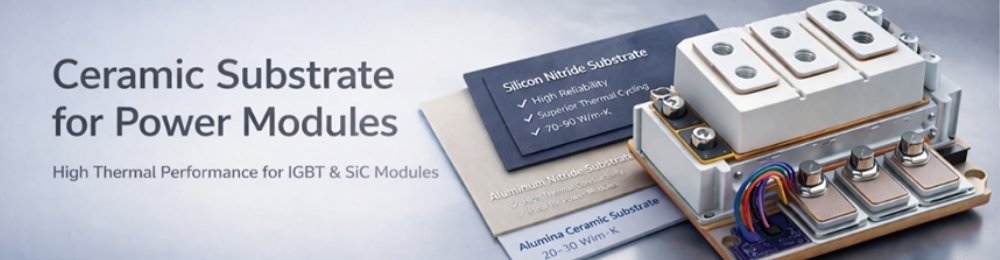 Fig.5-The typical applications of ceramic substrates
Industry Trends
Based on the evolving applications in the industry in recent years, the development of ceramic substrates exhibits the following major trends:
- As the power density of power modules continues to increase, heat dissipation requirements are constantly upgrading, leading to a gradual expansion in the application of AlN ceramic substrates.
- Si₃N₄, with its excellent reliability, is increasingly widely used in the new energy vehicle sector.
- With the industry’s ever-increasing demands for product reliability, the application ratio of AMB technology continues to climb;
- The widespread application of SiC and GaN devices is driving continuous upgrades in the requirements for substrate thermal performance and structural design.
From the perspective of overall industry development, material and process innovations in ceramic substrates are all advancing around the two core directions of “higher power density” and “higher reliability.”
Frequently Asked Questions(FAQs)
Q1. Which ceramic substrate is most suitable for IGBT power modules?
A: Silicon nitride (Si3N4) ceramic substrates are generally preferred for IGBT power modules due to their excellent thermal cycling resistance and mechanical strength. Aluminium nitride (AlN) can also be chosen for applications with high heat dissipation requirements.
Engineering insight: Si3N4 substrate is preferred for high reliability, while AlN substrate is preferred for high thermal conductivity requirements.
Why do electric vehicles tend to use silicon nitride substrates? To learn more, please see here.
Q2. What are the differences between Al2O3, AlN, and Si3N4 ceramic substrates? How to choose?
A: Al2O3 substrate has a lower cost and is suitable for general applications; AlN one has excellent thermal conductivity; Si3N4 performs better in terms of reliability and thermal shock resistance. The specific choice depends on power density and lifespan requirements.
Engineering insight: The selection process is essentially a comprehensive balance between cost, performance, and reliability.
Q3. Why must power modules use ceramic substrates?
A: Ceramic substrates possess both high thermal conductivity and high insulation properties, meeting the demands of high-voltage, high-power applications. They are a key component that traditional materials cannot replace.
Engineering insight: Ceramics are the only material that simultaneously solves the problems of heat dissipation and insulation.
Q4. Why do ceramic substrates in power modules fail?
A: Common causes include thermal stress accumulation, internal material defects, and fatigue caused by long-term thermal cycling, which can lead to cracking, peeling, or insulation breakdown.
Engineering insight: Most failures stem from a mismatch between material and structural design.
To learn about the root cause of copper layer peeling in DBC, please click here.
Q5. How to choose a suitable ceramic substrate for high-power applications?
A: It requires comprehensive consideration of thermal conductivity, mechanical strength, thermal cycling resistance, and voltage rating, rather than a single parameter.
Engineering insight: Thermal paths and structural design should be optimised at the system level.
Q6. Which ceramic material has the best thermal conductivity?
A: Among common ceramic materials, aluminum nitride (AlN) has the highest thermal conductivity, generally between 170–200 W/m·K, making it suitable for high heat dissipation applications.
Engineering insight: Thermal conductivity needs to be comprehensively evaluated in conjunction with reliability requirements.
Engineering Support
If you are designing a power module, we recommend finalising the substrate design early in the process to minimise later adjustments. Please provide the following parameters:
- Power rating
- Voltage level
- Cooling method
- Structural details
Based on these, we will identify more suitable materials and structural solutions to help the project progress smoothly.
Related Articles:
Comparison of DBC and AMB process differences
Comparison of Al₂O₃, AlN, and Si₃N₄ selections in power modules
Why do new energy vehicles prefer silicon nitride substrates
How to control ceramic substrate warpage
Root cause analysis of copper layer peeling in DBC
Common failure modes of power module ceramic substrates
Detailed explanation of the ceramic substrate manufacturing process (bare substrate)
How to select a suitable ceramic substrate
How ceramic substrates improve heat dissipation for power electronics